


 FE Courses
 PE Courses
 SE Courses
 Continuing Education
 Pmp Courses
 Corportate Training
Ever wonder what makes electronics tick? What goes inside circuits and systems that make everything work? Every electronic system consists of three major elements: voltage, current, and resistance. In this blog, we will explore resistance, what it is, its history, and how to use it.
In this Blog,
History
Electrical resistance was first discovered and formulated by German physicist Georg Simon Ohm in 1827. Ohm's groundbreaking work, Ohm's Law, laid the foundation for understanding the relationship between voltage, current, and resistance in electrical circuits. His invention of the resistor, a device specifically designed to provide a controlled amount of resistance in an electrical circuit, revolutionized the field of electrical engineering.
Resistor
A resistor is simply a passive two-terminal element that reduces current flow and divides voltages. Imagine a water pipe where the flow of water is equal to an electrical current. The flow is reduced when the diameter of the pipe is reduced, adding resistance into the system.
Resistor in Series
A series of resistors is when a resistor is connected from one terminal to another in succession in an electrical circuit. This arrangement is known as resistors in series, as shown in Figure 1. In this configuration, the total resistance is the sum of the individual resistances (Riedel & Nilsson, 2015, 58).
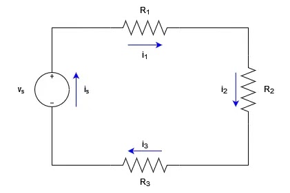 |
| Figure 1 |
Due to the nature of series circuit, the current in a closed loop equals the current source (is )
is = i1 = i2 = i3 (1)
By applying Kirchhoff's voltage law (KVL), the voltage (vs)can be obtained by,
-vs + isR1 + isR2 + isR3 = 0 (2)
vs = is(R1 + R2 + R3) (3)
Therefore, the equivalent resistance is,
Req = R1 + R2 + R3 (4)
Resistor in Parallel
Contrary to resistors in series, resistors in parallel are connected with both terminals side by side in a circuit. In this configuration, the total resistance is calculated differently. The reciprocal of the total resistance is equal to the sum of the reciprocals of the individual resistances (Riedel & Nilsson, 2015, 59). Parallel resistors allow current to divide among multiple paths, providing flexibility and load-sharing capabilities in electrical systems.
 |
| Figure 2 |
Due to the nature parallel circuit, the voltage across each resistor equals the source voltage (vs)
vs = vR1 = vR2 = vR3 (5)
iR1R1 = iR2R2 = iR3R3 = vs (6)
iR1 = vs/R1; iR2 = vs/R2; iR3 = vs/R3 (7)
By applying Kirchhoff’s current law (KCL), the current (is) can be obtained by,
is = iR1 + iR2 + iR3 (8)
Apply Equation 7 to Equation 8, we have a new equation:
is = vs(1/R1 + 1/R2 + 1/R3) (9)
from which the equivalent resistance is,
is/vs = 1/Req = 1/R1 + 1/R2 + 1/R3 (10)
A quick tip to find the equivalent resistance when we are dealing with only two resistors connected in parallel: the equivalent resistance can be obtained by dividing the product of the resistances by their sum. It is important to note that this formula is applicable exclusively to the specific scenario of two resistors in parallel (Riedel & Nilsson, 2015, 60).
 |
| Figure 3 |
From Figure 3, the equivalent resistance is,
Req = R1R2/R1 + R2 (11)
Voltage Divider
A voltage divider is a circuit that divides the input voltage into smaller, adjustable voltages. It consists of resistors connected in series. By varying the resistance values, we can control the output voltage across specific resistors, enabling us to power different components with varying voltage requirements.
 |
| Figure 4 |
We use Kirchhoff's voltage law (KVL) and Kirchhoff's current law (KCL); a blog about these two can be found in "What Is Voltage Law" to derive the voltage (v1 and v2) from Figure 4 (Riedel & Nilsson, 2015, 61).
vs= iR1 + iR2 (12)
i = vs/ R1 + R2 (13)
Apply Equation 13 to the voltage equation v1 and v2 :
v1 = iR1 = vs (R1/R1 + R2)(14)
v2 = iR2 = vs (R2/R1 + R2)(15)
Current Divider
Similar to voltage dividers, current dividers allow the division of current among different paths. By using resistors in parallel, we can distribute the total current into smaller currents that flow through individual branches of the circuit. This technique finds applications in situations where precise current allocation is needed.
 |
| Figure 5 |
From Equation 11, we can obtain the voltage (v) from Figure 5.
v = ( R1R2/R1 + R2) is (16)
From Ohm's law, we know the voltage across the two resistors are,
v = i1R1 = i2R2 (17)
Replacing Equation 16 into Equation 17, we have
i1 = ( R2/R1 + R2) is (18)
i2 = ( R1/R1 + R2) is (19)
Equation 18 and Equation 19 demonstrate that when two resistors are connected in parallel, the current splits in such a way that the current flowing through one resistor is equal to the total current entering the parallel combination, multiplied by the resistance of the other resistor, and divided by the sum of the resistances (Riedel & Nilsson, 2015, 63).
Measure Voltage and Current
To understand and analyze electrical circuits, it is essential to measure voltage and current accurately. Voltage can be measured using a voltmeter, a device connected in parallel across a component to measure the potential difference. Current, on the other hand, is measured using an ammeter, which is inserted in series with the component to measure the flow of electrons (Riedel & Nilsson, 2015, 66).
Now, we have a multimeter (Figure 6) which can measure both the voltage, current, and other aspects. You can check out this website on how to utilize the multimeter properly.
 |
| Figure 6 |
Conclusion
Electrical resistance, a concept rooted in the works of Georg Simon Ohm, plays a vital role in understanding and manipulating electrical circuits. From resistors in series and parallel to voltage dividers and current dividers, each concept opens a realm of possibilities in electrical engineering. By effectively measuring voltage and current and employing delta to wye conversions, engineers can design and analyze complex electrical networks. Embrace the power of electrical resistance and unlock the true potential of modern technology.
Amplify your electrical engineering exam prep with School of PE. Our comprehensive courses come with what you need to succeed on exam day! Check out our FE Electrical or PE Electrical exam review courses now.
References
Riedel, S. A., & Nilsson, J. W. (2015). Electric Circuits. Pearson.
No comments :
Post a Comment