


 FE Courses
 PE Courses
 SE Courses
 Continuing Education
 Pmp Courses
 Corportate Training
Index:
History
In 1831, English natural philosopher Michael Faraday discovered electromagnetic inductance. From his discovery, he noted that when a current flows through a conductor, a magnetic field is produced around it. This resulting magnetic field also induces an electromagnetic force (EMF) in the same conductor, which opposes the current flow. This phenomenon is called self-induction or simply inductance.
Despite being originally discovered by Faraday, Joseph Henry, an American scientist, was credited for making significant contributions to the development of electromagnetism, leading to the unit of measurement for an inductor to be named after Henry. Working independently of Michael Faraday, Henry demonstrated that an electric current could be induced in a coil of wire by a changing magnetic field, setting up the groundwork and foundation for future developments of inductors and transformers (Whelan et al., n.d.). The unit "Henry" was first proposed in 1893 by the International Electrical Congress and was later adopted as the standard unit of inductance by the International System of Units (SI) in 1946.
What Is an Inductor?
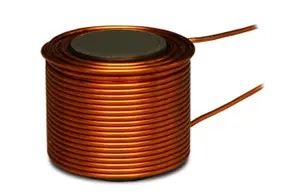
An inductor is a passive element, which stores energy in its magnetic field when energized (Figure 1). It is typically made with coiled wire wrapped around a conductive metal core. An inductor opposes the changes in the current passing through it. The shape of the core can vary depending on the type of inductor, but the most common shapes are cylindrical, toroidal, and rectangular.

Figure 1
Inductance is a circuit parameter that describes an inductor and is measured in henrys (H), and the letter L represents inductance. The passive sign convention is used to assign the current reference direction in the direction of the voltage drop across the inductor, as shown in Figure 2.

Equation 1 reflects this convention, and if the current reference is in the direction of the voltage rise, it is written with a minus sign.
v = L di/dt (1)
The voltage across an inductor's terminals is proportional to the rate of change of the current flowing through the inductor, as shown in Equation 1. From this equation two observations can be made from this relationship.
If the current is constant, then the voltage across an ideal inductor is zero, making it behave as a short circuit in the presence of a constant or DC current.
If the current cannot change instantaneously in an inductor, then it is impossible to change it by a finite amount in zero time.
From the above observations, an infinite voltage will theoretically be generated if infinite self-inductance occurs, which is physically impossible (Nilsson & Riedel, 2015, 176).
We can rearrange Equation 1 to obtain the current equation.
i(t) = 1/L ∫0t vdx + i(t0) (2)
The inductor energy equation can be expressed as:
w = 1/2 Li2 (3)
Inductance Connection
For the simplicity
1. Series
In a series connection, inductors are connected from end-to-end (Figure 3) so that the current flows through each inductor remain the same, similar to resistors being connected in series. The inductors can be simplified to a single equivalent inductor. It can be achieved by summing the individual inductances (Nilsson & Riedel, 2015, 187).

Figure 3
The equivalent inductance equation can be expressed as:
Leq = L1 + L2 + ... + Ln (4)
The voltage across the terminal can be found by summing the voltage of each inductor:
v = vL1 + vL2 +...vLn (5)
2. Parallel
In a parallel connection, the inductors are connected side-by-side (Figure 4) and can be simplified into an equivalent circuit by summing the reciprocals of each inductor's inductance.

Figure 4
The equivalent inductance can be expressed as:
1/Leq = 1/L1 + 1/L2 + ... + 1/Ln (6)
From Figure 3, we can observe the terminal current equals the sum of the other inductor currents.
i = iL1 + iL2 + ... + iLn (7)
Types of Inductors
Here, we will introduce three of the most common types of inductors in use: air-core inductors, iron-core inductors, and toroidal inductors.
1. Air-core Inductor: Air-core inductors are different from the other two inductor types because they are made with a coil of wire wrapped around a non-magnetic core, like plastic or ceramic. This type of inductor is used in high-frequency applications, where its low inductance and low loss make it an ideal choice. These are often used in radio tuning circuits.

2. Iron-core Inductor: Iron-core inductors are made with a coil of wire wrapped around a ferromagnetic core, like iron or ferrite. With a higher inductance and high saturation flux density, this inductor type is commonly used in low-frequency applications. These are often used in power supply and audio circuits.
3. Toroidal Inductor: Toroidal inductors are made with a coil of wire wrapped around a toroidal (ring) core; this core is typically made of iron or ferrite. This shape allows for a lighter-weight design and higher inductance. This inductor type is commonly found in noise filtering and power supplies.

Application
Thanks to inductors, engineers have been able to utilize its energy storage in multiple real-world applications.
1. Filter
An inductor's ability to prevent instant current changes ensures a constant voltage output. A filter circuit consists of an inductor and a capacitor to smooth out the DC voltage, ensuring a stable and regulated power supply.
Not only are they used to filter noise from the current of a power circuit, but inductors are also used to filter out unwanted signals and noise. A choke coil, which is a type of inductor, is used to block high-frequency noise and prevent it from entering the audio amplifier.
2. Transformer
A transformer is a device that transfers electrical energy from one circuit to another through the properties of electromagnetic induction. A transformer consists of two or more coils of wire wrapped around a ferromagnetic core. Transformers are used to step up or step-down voltage levels in AC power supply circuits, making them essential for the transmission and distribution of electrical power.
Conclusion
Inductors are electronic components that store electric energy through their magnetic fields. Through them, we can filter out unwanted noises in power and signals and transfer and manage electrical energy across a circuit. They are essential for the proper functioning of power supply circuits, transformers, audio circuits, radio circuits, and oscillators, among other applications.
Looking to electrify your electric engineering exam prep? Don't miss School of PE's FE and PE Electrical exam prep courses. Register now on www.schoolofpe.com.
References
Nilsson, J. W., & Riedel, S. A. (2015). Electric Circuits. Pearson.
Whelan, M., Reilly, E., & Rockwell, S. (n.d.). Joseph Henry - Engineering Hall of Fame. Edison Tech Center. Retrieved May 9, 2023, from https://edisontechcenter.org/JosephHenry.html
No comments :
Post a Comment