Thursday, 25 January 2024

The Great Golden Gate: A Reflection on San Francisco’s Iconic Bridge

The Golden Gate Bridge is an iconic symbol that stands tall and majestic in the skyline of San Francisco, captivating visitors with its grandeur and engineering marvel. Engineers in the past and present have graced humanity with many wonders through sheer ingenuity and creativity, but this iconic bridge stands out. This blog aims to inform and describe the fascinating story behind the construction of this renowned bridge, its purpose and design, the struggles faced during its building process, and the individuals involved in its creation.
History
In 1916, James H. Wilkins, a structural engineer, made the first serious proposal for a bridge across the Golden Gate Strait, connecting the city of San Francisco to Marin County, California. Wilkins' proposal was not new: the concept of a bridge spanning the Golden Gate had been discussed since Charles Crocker's call for a bridge in 1872, but plans had been disrupted by the Great 1906 San Francisco earthquake.
Wilkins' campaign caught the attention of San Francisco City Engineer Michael M. O'Shaughnessy. The city officials formally requested O'Shaughnessy to explore the feasibility of such a bridge in August 1919.
O'Shaughnessy then went off and consulted various engineers across the United States for their opinions on the feasibility and cost of the project. Many engineers believed that building a bridge that expansive would cost well over $100 million and deemed it impossible. However, Joseph Baermann Strauss stepped forward with a different view. He not only believed that constructing the bridge was feasible but also estimated that it could be built for $25 to $30 million (Anagnos & Sheppard, n.d.).
On December 4, 1928, the Golden Gate Bridge and Highway District was formed, and on August 11, 1930, all authorizations and permits were finalized. By 1937, the 1.7-mile-long bridge was finally completed $1.3 million under budget (U.S. Department of Transportation, n.d.).
The bridge held the world record for the longest suspension span for 27 years.
Purpose and Significance
The primary purpose of constructing the Golden Gate Bridge was to provide an accessible transportation route for both vehicular and pedestrian traffic between the city of San Francisco and Marin County. Before the bridge's completion in 1937, crossing the Golden Gate Strait was a time-consuming and risky endeavor, often relying on the use of ferry services to get across. The bridge's completion enhanced travel in the San Francisco Bay Area, significantly reducing commute times and enabling enormous economic growth in the region.
Engineering
1. Tower Height and Cable Tension
Engineers faced a critical challenge in the design of the Golden Gate Bridge, needing to strike a balance between tower height and cable size. One consideration was reducing the tension force in the cables and cable size, which could be achieved by constructing taller towers (Figure 1) (Anagnos & Sheppard, n.d.). However, opting for significantly taller towers presented a more complex and costly design alternative.
In an effort to address this challenge, engineers utilized galvanized carbon steel wire for the cables. This choice allowed for a strong and durable cable system while maintaining a practical size. Galvanization, a process that involves coating the steel cable with a protective layer of zinc, enhanced the cables' resistance to corrosion, extending their lifespan and ensuring the bridge's long-term structural integrity.
Below is one of many equations that were used to calculate the tension and compression arches in the bridge. Equation 1, a parabolic formula, is used to calculate the shape of both the tension and compression arches:
y = kx2          (1)
Noted in the construction of this suspension bridge is a prominent sag; the sag of the suspension cable controls the stability of the bridge and ensures equal weight distribution across the bridge.
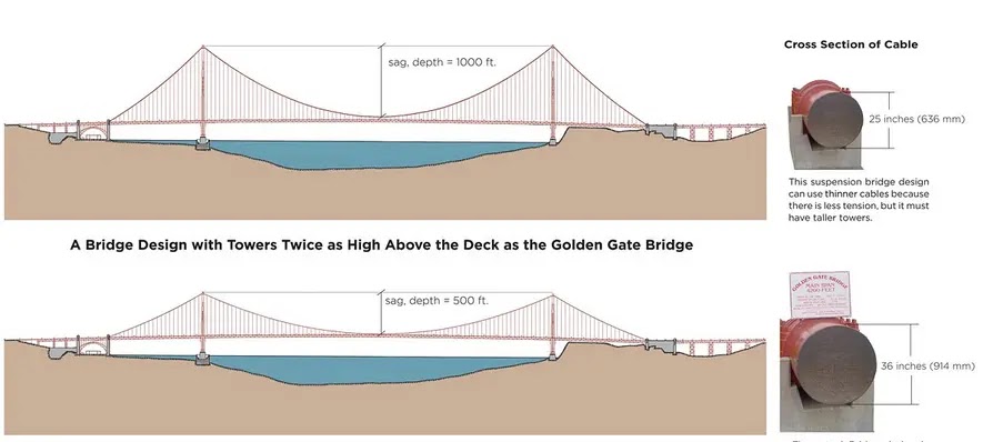
Tower Height and Cable Tension
Figure 1
To learn more about bridge cable tension and math equations utilized for the project, you can visit this website.
2. Understanding the Aerodynamics of Bridge Deck
The stability of a suspension bridge in strong winds is determined by factors such as the weight, torsional stiffness, and the shape of its cross-section. Even subtle changes to the cross-sectional shape can have a significant impact on the bridge's stability.
This was exemplified by the collapse of the Tacoma Narrows Bridge in 1940. On a moderately windy day, the bridge collapsed due to its cross-sectional shape's inability to withstand the wind forces. A scale model of the collapsed Tacoma Narrows Bridge is compared to a modern design in another model. Both models have similar stocky cross-sections in terms of height and width. However, when exposed to wind, the model of the Tacoma Narrows Bridge twists violently, while the model with a stable cross-sectional shape remains relatively unaffected by gusts (Anagnos & Sheppard, n.d.).
The Golden Gate Bridge applies the modern aerodynamically designed bridge (Figure 2) for the deck to stabilize the bridge.
Understanding the Aerodynamics of Bridge Deck
Figure 2
3. Counteracting Torsional Forces by Bracing System
Engineers have long grappled with the issue of excessive movement in modern suspension bridges, dating back to their invention in the early 1800s. The Golden Gate Bridge faced a similar challenge during a storm on December 1, 1951, when it experienced significant twisting and vibrations that resulted in minor damage. As a response, the bridge underwent retrofitting from 1953 to 1954. The retrofitting involved the addition of new bracing, which connected the two steel trusses supporting the roadway deck (the right-hand side of Figure 3). This modification notably enhanced the bridge's torsional stiffness, reducing the extent of twisting during adverse weather conditions (Anagnos & Sheppard, n.d.).
Counteracting Torsional Forces by Bracing System
Figure 3
For more engineering aspects, you can find it here.
Cost
The contract awarded through a successful bidding process offers a detailed breakdown of the cost, as illustrated in Figure 4 (Loomis, 1958, p. 133). Subsequently, in Figure 5, we will present the ultimate expenditure incurred for the construction of the bridge (Loomis, 1958, p. 189).
Cost-1
Figure 4
Cost-2
Figure 5
Conclusion
The Golden Gate Bridge stands as a testament to human ingenuity, engineering prowess, and determination. From its conception by Joseph Strauss to the collaboration between Charles Ellis and Irving Morrow, the bridge's design and construction represent a remarkable achievement in the field of civil engineering. Despite facing challenges during its construction, the Golden Gate Bridge now serves as an enduring symbol of San Francisco and a testament to the power of human endeavor.
Curious about becoming an engineer yourself? Check out School of PE's FE and PE exam review courses, all of which can help you on your journey to professional licensure.
References
Anagnos, T., & Sheppard, S. (n.d.). Suspension Cable Tension vs. Tower Height - Exhibit Area 4 | Golden Gate. Golden Gate Bridge, Highway and Transportation District. Retrieved May 22, 2023, from https://www.goldengate.org/exhibits/suspension-cable-tension-vs-tower-height/
Loomis, R. T. (1958, October). A Dissertation Submitted to the Department of History and the Comittee on Graduate Study of Standford University. https://www.goldengate.org/assets/1/6/loomis_dissertation_1958.pdf
U.S. Department of Transportation. (n.d.). Golden Gate Bridge Fact Sheet. Retrieved May 31, 2023, from https://www.fhwa.dot.gov/candc/factsheets/goldengatebridge.pdf
About the Author: Khoa Tran

Khoa Tran is an electrical engineer working at the Los Angeles Department of Water and Power and is currently pursuing his master's in electrical Power from the University of Southern California. He is fluent in both Vietnamese and English and is interested in outdoor activities and exploring new things.

Thursday, 18 January 2024

Emerging Technologies: The History and Mission of Neuralink

Neuralink
On May 25, 2023, Neuralink, a company founded by business magnate tech Elon Musk, received approval from the United States Food and Drug Administration (FDA) to conduct in-human trials for a brain-machine interface (BMI) chip.
In this blog, we will go over what Neuralink is, its intent, its history, and the significance of it receiving approval to conduct in-human trials.
Introduction
What is Neuralink?
To begin, who is the brains of this company? Elon Musk is a billionaire investor and owner of several innovative companies: Tesla, SpaceX, The Boring Company, and Neuralink. With a simple mission statement, Musk's goal for Neuralink is to "create a generalized brain interface to restore autonomy to those with unmet medical needs today and unlock human potential tomorrow."
As the name implies, a brain-machine interface is a device that allows communication between the brain and external software or hardware, such as a computer or prosthetic. With the use of BMI, scientists and engineers are able to restore or replace functionality to people who have been disabled neurologically, physically, or by any other means.
Now, let us go over what the company actually does. Neuralink aims to develop a BMI technology that can seamlessly connect the human brain with computers. The primary goal is to enhance human cognition and to create a direct, high-bandwidth link between humans and the digital devices around us.
In addition to communication with electronics, Neurolink also addresses various neurological conditions and disorders, by enabling better understanding and treatment of brain-related ailments. Some of the potential applications include (Neuralink, n.d.):
  1. Restoring lost sensory functions: Neuralink could potentially help individuals with sensory impairments, such as blindness or deafness by directly stimulating the relevant areas of the brain to bypass damaged sensory organs.
  2. Treating neurological disorders: The technology could provide new ways to treat conditions such as epilepsy, Parkinson's disease, and other neurological disorders by modulating brain activity or delivering targeted therapies.
  3. Enhancing cognitive abilities: Neuralink has the potential to augment human cognition by creating a more direct and efficient interface between the brain and computers. This could enable faster communication, enhanced memory, and even the ability to directly access instant information from the internet.
  4. Improving human-computer interactions: With a brain-machine interface, individuals could potentially control computers or digital devices with their thoughts, eliminating the need for physical input devices and enabling a more seamless interaction.
  5. Advancing artificial intelligence (AI): Neuralink's technology could facilitate the integration of AI systems with the human brain, allowing for enhanced collaboration and improved problem-solving capabilities.
Surgical Step
Surgical Step
The process of installing the Neuralink chip in the human brain involves the following steps:
  1. Pre-operative planning: Detailed imaging techniques are used to map the brain's structure and identify target areas for implantation.
  2. Anesthesia: The patient undergoes general anesthesia to ensure they are unconscious and do not feel any pain during the procedure.
  3. Burr hole creation: A specialized drill creates a small hole in the skull at a predetermined location based on pre-operative planning.
  4. Insertion of the Neuralink device: The Neuralink chip, approximately the size of a coin, is inserted through the burr hole into the brain. A robotic surgical system is often used for precision and minimal tissue damage. Fine threads or electrodes attached to the chip are gently implanted into the brain tissue to establish neural connections.
  5. Closing the incision: Once the Neuralink device is in place, the incision in the skull is closed using sutures or staples. The device is designed to sit flush with the skull, leaving no visible hardware outside the body.
The Good vs Bad
Neuralink, like any emerging technology, has potential benefits and challenges. Here are some potential pros and cons associated with Neuralink:
Pros:
  1. Medical advancements: Neuralink could offer significant medical benefits by providing new ways to treat neurological disorders, restore lost sensory functions, and improve overall brain health and cognition.
  2. Enhanced human capabilities: With a brain-machine interface, individuals could potentially have access to advanced computing power, memory enhancements, and improved communication, enabling new levels of human achievement and collaboration.
  3. Improved human-computer interaction: Neuralink could revolutionize how humans interact with computers and digital devices, allowing for seamless and intuitive control through direct brain-computer interfaces.
  4. Potential for scientific research: The technology could provide researchers with new insights into the workings of the human brain, leading to advancements in neuroscience and our understanding of cognition.
Cons:
  1. Surgical risks and safety concerns: The implantation of the Neuralink device requires a surgical procedure, which comes with inherent risks such as infection, bleeding, or damage to brain tissue. Ensuring the safety and reliability of the technology will be a critical consideration.
  2. Ethical considerations: The development of brain-machine interfaces raises ethical questions, such as privacy concerns regarding the collection and storage of sensitive neural data, potential misuse of the technology, and questions about consent and human augmentation.
  3. Accessibility and equity: Neuralink, in its early stages, may be expensive and accessible to only a select few, potentially exacerbating existing inequalities in healthcare and opportunities for enhancement.
  4. Long-term effects and unknown risks: As Neuralink is a relatively new technology, the long-term effects on the brain and the potential risks associated with chronic implantation are not yet fully understood. Thorough research and rigorous testing are necessary to ensure the safety and efficacy of the technology.
Conclusion
The installation of the Neuralink chip in the human brain involves a surgical procedure that aims to establish a direct interface between the brain and computers. Through pre-operative planning, anesthesia, burr hole creation, insertion of the Neuralink device, and closing the incision, a team of medical professionals works to implant the chip and establish neural connections within the brain.
This procedure represents a significant advancement in the field of brain-machine interfaces and holds the potential to enhance human cognition, treat neurological disorders, and revolutionize human-computer interaction. However, further research, rigorous testing, and ethical considerations are necessary to ensure the safety, efficacy, and accessibility of this technology. As Neuralink continues to develop and refine its approach, the future holds both promises and challenges in the realm of neural connectivity and its potential impact on human lives.
References
Neuralink. (n.d.). Neuralink. Retrieved June 1, 2023, from https://neuralink.com/#mission
About the Author: Khoa Tran

Khoa Tran is an electrical engineer working at the Los Angeles Department of Water and Power and is currently pursuing his master's in electrical Power from the University of Southern California. He is fluent in both Vietnamese and English and is interested in outdoor activities and exploring new things.

Thursday, 11 January 2024

Decoding the FE Exam: Your Ultimate Guide to Success

The Fundamentals of Engineering (FE) exam, or the Engineer in Training (EIT) exam, is the crucial first step towards obtaining a Professional Engineering (PE) license in the United States. The FE exam is a computer-based exam designed to test an engineer's cumulative knowledge and skills. There are various disciplines to choose from, including civil, mechanical, and electrical engineering. The intent of this blog is to properly explore what the FE is, what is covered in the general examination, and what other specialized exams an engineer can take.
What Is the FE
Designed for recent graduates and students who are on their way to finishing their undergraduate engineering degree, the FE is a computer-based exam offered year-round by the National Council of Examiners for Engineering and Surveying (NCEES). It is the first of two exams that an engineer will need to pass in order to obtain their PE license in the United States.
Covering the fundamentals of engineering, the FE will test an examinee's knowledge in a wide range of topics, including mathematics, ethics, and professionalism. It is a 110-question exam that needs to be completed within approximately 5 and a half hours. Participants are not allowed cheat sheets during the exam, but they are provided with a virtual reference handbook, which can be obtained earlier and reviewed using the instructions from the "How to get the latest FE Reference Handbook" blog.
Now, let us go over the different types of FE that an engineer can take.
FE General
The FE General, or Other Disciplines, exam is unique compared to the other available exams because it is not discipline-specific, meaning that it does not test advanced engineering principles in a particular field. The exam will cover various engineering topics, such as mathematics, statistics, chemistry, ethics, and safety.
While not discipline-specific, the general examination will test on topics from the other specifications: strength of materials, fluid mechanics, basic electrical engineering, and thermodynamics and heat transfer.
As of January 2023, the passing rate for the FE General exam was recorded to be 55%, according to the NCEES.
FE Civil
For those who are interested in obtaining their EIT certification or PE license in civil engineering, there is a discipline-specific FE exam designed with them in mind, the FE Civil exam. While still testing the same general topics of the FE Other Disciplines exam, the Civil exam is more geared toward the field of civil engineering. Examinees will be questioned on their knowledge of surveying, water resources and environmental engineering, structural engineering, transportation, and construction.
Civil engineers are highly encouraged or required to take the FE. Without holding an EIT certification, civil engineers may be disqualified for promotions and other job opportunities. It is crucial for those who want to advance in their career as a civil engineer to pass the FE or even obtain their PE license.
FE Civil
As of Jan 2023, the passing rate for the FE Civil exam was recorded to be 55%, according to the NCEES.
FE Mechanical
For those who are looking to become a PE in mechanical engineering, they must pass the FE Mechanical exam. Again, this discipline-focused exam will still cover the same general topics as the FE Other Disciplines exam; however, as the name implies, this exam will focus more on topics required in the field of mechanical engineering. Examinees will be tested on their knowledge and understanding of Statics, Kinematics, Mechanics and Materials, and Mechanical Design and Analysis.
While not a requirement, like for civil engineers, mechanical engineers are still encouraged to pursue their PE for more career opportunities and salary raises.
FE Mechanical
As of Jan 2023, the passing rate for the FE Mechanical exam was recorded to be 65%, according to the NCEES.
FE Electrical
Before becoming a PE in electrical engineering, you must first pass the FE Electrical & Computer exam. Unlike the previous two discipline-specific FEs, the Electrical and computer exam covers topics for both electrical engineering and computer engineering.
However, like all other discipline-focused FEs, the Electrical and Computer FE will test for the same general topics that the FE Other Disciplines exam covers. Examinees for this exam will have to study the Properties of Electrical Materials, Circuit Analysis, Power Systems, Computer Systems, and Software Engineering.
For electrical engineers, the requirement for a PE varies depending on the job and industry that they are pursuing. For example, those working in product development will not need to take the PE, while those in public power generation will.
FE Electrical
As of Jan 2023, the passing rate for the FE Electrical and Computer exam was recorded to be 64%, according to the NCEES.
Conclusion
The FE exams are essential for anyone who wants to become a licensed Professional Engineer in the United States. While the general FE exam covers a broad range of engineering topics, the FE Civil, Mechanical, and Electrical exams are designed to test a candidate's knowledge of specific engineering principles and concepts. The examples provided demonstrate the importance of choosing the correct exam to match the candidate's chosen field of study and ensure they have a comprehensive understanding of the discipline-specific knowledge required to become a licensed Professional Engineer.
Moreover, taking any FE exam can lead to improved job prospects, higher salaries, and greater opportunities for career advancement, reflecting the value and recognition of the PE license in the related engineering industry. Additionally, passing the exam can provide a sense of personal accomplishment and satisfaction, indicating the individual's dedication, discipline, and intelligence in the field of engineering.
If you are planning to take the FE exam, you want to be confident that you are fully prepared to tackle its challenging questions. This is where School of PE comes in. They offer a variety of review courses specifically designed to help you succeed in any type of FE exam, whether it is the general FE, FE Civil, FE Mechanical, or FE Electrical exam. With experienced instructors and a comprehensive curriculum that covers all the necessary topics, you can rest assured that you'll be well-equipped to ace the exam. So, whether you are a recent graduate or a seasoned professional looking to take your career to the next level, School of PE has the tools and resources you need to achieve your goals. Check out our exam prep options today!
About the Author: Khoa Tran

Khoa Tran is an electrical engineer working at the Los Angeles Department of Water and Power and is currently pursuing his master's in electrical Power from the University of Southern California. He is fluent in both Vietnamese and English and is interested in outdoor activities and exploring new things.

Thursday, 4 January 2024

Waving Hello: Exploring Electromagnetic Radiation

Radiation surrounds us in our daily lives, but don't be fooled: not all types of radiation are harmful to us. The visible light spectrum is a type of electromagnetic radiation that is harmless to humans and can be perceived with the naked eye. The electromagnetic spectrum is the range of all types of electromagnetic radiation. It is important to understand this spectrum, as it allows us to utilize the different types of radiation and their properties for various scientific advancements.
History
The electromagnetic spectrum was not discovered overnight by just one scientist but was a collaborative effort of centuries' worth of hypotheses and experimentations. Contributions by scientific pioneers such as James Clerk Maxwell, Heinrich Hertz, and others were crucial in shaping our modern understanding of electromagnetic radiation and its many forms.
Beginning around 1820, Danish physicist Hans Christian Ørsted discovered that electric currents produce magnetic fields, inventing the field of electromagnetism. In 1865, Maxwell's equations provided a theoretical framework for understanding the behavior of electromagnetic waves and demonstrated that they travel at the speed of light (Freedman et al., 2012, 1052). Later, in the late 19th century, Hertz conducted experiments that first confirmed Maxwell's theories and proved the existence of electromagnetic waves and radio waves, which paved the way for the development of radio technology (Freedman et al., 2012, 1053).
Electromagnetic Spectrum
The electromagnetic spectrum is a term used to categorize the range of electromagnetic radiation; electromagnetic radiation is a type of energy that is propagated through space in the form of waves. These waves are characterized by their wavelength and frequency, and they include radio waves, microwaves, infrared radiation, visible light, ultraviolet radiation, X-rays, and gamma rays (National Aeronautics and Space Administration, 2013).
Type of Spectrum
We encounter electromagnetic radiation in our everyday lives. These types of radiation can be classified into radio waves, microwaves, infrared, visible light, ultraviolet, x-rays, and gamma rays.
Waving Hello: Exploring Electromagnetic Radiation
  1. Radio: Radio waves have a very long wavelength, ranging from about 1 millimeter to 100 kilometers. Due to their long wavelength, radio waves can travel long distances without being absorbed by the atmosphere, making them ideal for communication. Some of its many real-world applications include broadcasting, navigation, and satellite communication (National Aeronautics and Space Administration, 2016).
  2. Microwave: Microwaves have a shorter wavelength than radio waves, between 1 meter to 1 millimeter. Microwaves can be found used widely in modern life, famously for cooking, but also in communication technology and radar. They are commonly used in microwave ovens for cooking food, where the microwaves interact with the water molecules in the food, causing them to vibrate and generate heat. Meanwhile, in communication technology, microwaves are used in various applications such as cell phones, Wi-Fi, and satellite communication. (National Aeronautics and Space Administration, 2016).
  3. Infrared: Infrared radiation (IR) has a shorter wavelength than both radio and microwaves, ranging between about 700 nanometers to 1 millimeter. IR radiation is not visible to the human eye, but it can be perceived as heat. IR radiation is used in night vision, thermal imaging, and remote sensing (National Aeronautics and Space Administration, 2016).
  4. Visible: Visible light, as the name implies, is the electromagnetic spectrum that is perceivable to the naked human eye. It has a wavelength range of approximately 400 to 700 nanometers and is characterized by its different colors: red, orange, yellow, green, blue, indigo, violet, and everything in-between. The colors of visible light are determined by the wavelength of the electromagnetic radiation, with longer wavelengths appearing as red and shorter wavelengths appearing as violet (National Aeronautics and Space Administration, 2016).
  5. Ultraviolet: Ultraviolet (UV) radiation has a shorter wavelength than visible light, ranging from about 10 to 400 nanometers. UV radiation, while not visible to the human eye, is harmful and can cause sunburn, skin damage, and skin cancer. It can be utilized in industrial and medical applications, such as sterilization and fluorescence microscopy (National Aeronautics and Space Administration, 2016).
  6. X-ray: X-rays range from about 0.01 to 10 nanometers. Because of their short wavelength, X-rays can penetrate through many materials, including human tissue. This property makes them ideal for medical imaging, such as X-ray radiography, computed tomography (CT) scans, and mammography (National Aeronautics and Space Administration, 2016).
  7. Gamma Ray: Gamma ray has the shortest wavelength and highest frequency within the electromagnetic spectrum. They are produced by the decay of radioactive atoms and by high-energy processes, such as nuclear fission, supernova explosions, black holes, and neutron stars (National Aeronautics and Space Administration, 2016).
Implications for Health and Safety
Due to its ranging wavelengths, cause for health and safety concerns arise with the use of electromagnetic radiation. For example, exposure to ultraviolet radiation from the sun can be very harmful, potentially leading to ocular damage and skin cancer. Additionally, there have been growing concerns about the potential health risks of exposure to radiation from cell phones, Wi-Fi, and other wireless devices. While there is currently no conclusive evidence linking electromagnetic radiation as a whole to adverse health effects, there have been studies suggesting a possible link to cancer and other health issues.
As such, it is important to be aware of the potential risks and take steps to minimize exposure, such as using protective clothing and sunscreen when in the sun and limiting cell phone use. It is also important for scientists to continue studying the effects of electromagnetic radiation on human health to ensure that we can use this powerful tool safely and responsibly.
Relationship
One important concept related to the electromagnetic spectrum is the relationship between wavelength and frequency. Wavelength and frequency are inversely proportional, meaning that as the wavelength of electromagnetic radiation increases, the frequency decreases and vice versa. This relationship is described by the equation (Freedman et al., 2012, 1054):
c = λf          (1)
where c is the speed of light at a value of 299,792,458 m/s, λ is the wavelength, and f is the frequency.
Conclusion
The electromagnetic spectrum encompasses the universe and can be utilized to assist us in our daily lives. From radio waves to gamma rays, each type of electromagnetic radiation has unique properties that allow us to develop new and innovative technologies. The relationship between wavelength and frequency is a fundamental concept in understanding the electromagnetic spectrum and how it behaves. As our understanding of the electromagnetic spectrum continues to evolve, we can expect to see new and exciting technologies emerge that take advantage of this incredible form of energy.
Are you ready to supercharge your engineering career? Consider taking an FE Electrical or PE Electrical exam review course with School of PE.
References
Freedman, R. A., Young, H. D., & Ford, A. L. (2012). Sears and Zemansky's University Physics: With Modern Physics (A. L. Ford, Ed.). Addison-Wesley.
National Aeronautics and Space Administration. (2013, March). Electromagnetic Spectrum - Introduction. Imagine the Universe! Retrieved May 14, 2023, from https://imagine.gsfc.nasa.gov/science/toolbox/emspectrum1.html
National Aeronautics and Space Administration. (2016, August 10). The Electromagnetic Spectrum Video Series & Companion Book. NASA Science. Retrieved May 14, 2023, from https://science.nasa.gov/ems/
About the Author: Khoa Tran

Khoa Tran is an electrical engineer working at the Los Angeles Department of Water and Power and is currently pursuing his master's in electrical Power from the University of Southern California. He is fluent in both Vietnamese and English and is interested in outdoor activities and exploring new things.

Friday, 29 December 2023

You Can’t Resist This: Exploring Resistance within Electronic Systems

Ever wonder what makes electronics tick? What goes inside circuits and systems that make everything work? Every electronic system consists of three major elements: voltage, current, and resistance. In this blog, we will explore resistance, what it is, its history, and how to use it.
History
Electrical resistance was first discovered and formulated by German physicist Georg Simon Ohm in 1827. Ohm's groundbreaking work, Ohm's Law, laid the foundation for understanding the relationship between voltage, current, and resistance in electrical circuits. His invention of the resistor, a device specifically designed to provide a controlled amount of resistance in an electrical circuit, revolutionized the field of electrical engineering.
Resistor
A resistor is simply a passive two-terminal element that reduces current flow and divides voltages. Imagine a water pipe where the flow of water is equal to an electrical current. The flow is reduced when the diameter of the pipe is reduced, adding resistance into the system.
Resistor in Series
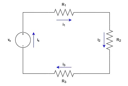
A series of resistors is when a resistor is connected from one terminal to another in succession in an electrical circuit. This arrangement is known as resistors in series, as shown in Figure 1. In this configuration, the total resistance is the sum of the individual resistances (Riedel & Nilsson, 2015, 58).
Resistor in Series
Figure 1
Due to the nature of series circuit, the current in a closed loop equals the current source (i)
is = i1 = i2 = i3 (1)
By applying Kirchhoff's voltage law (KVL), the voltage (vs)can be obtained by,
-vs + isR1 + isR2 + isR3 = 0 (2)
vs = is(R1 + R2 + R3) (3)
Therefore, the equivalent resistance is,
Req = R1 + R2 + R3 (4)
Resistor in Parallel
Contrary to resistors in series, resistors in parallel are connected with both terminals side by side in a circuit. In this configuration, the total resistance is calculated differently. The reciprocal of the total resistance is equal to the sum of the reciprocals of the individual resistances (Riedel & Nilsson, 2015, 59). Parallel resistors allow current to divide among multiple paths, providing flexibility and load-sharing capabilities in electrical systems.
Resistor in Parallel
Figure 2
Due to the nature parallel circuit, the voltage across each resistor equals the source voltage (vs)
vs = vR1 = vR2 = vR3 (5)
iR1R1 = iR2R2 = iR3R3v(6)
iR1 = vs/R1; iR2 = vs/R2; iR3 = vs/R3 (7)
By applying Kirchhoff’s current law (KCL), the current (is) can be obtained by,
i = iR1 + iR2 + iR3 (8)
Apply Equation 7 to Equation 8, we have a new  equation:
is = vs(1/R1 + 1/R2 + 1/R3) (9)
from which the equivalent resistance is,
is/vs = 1/Req = 1/R1 + 1/R2 + 1/R3 (10)
A quick tip to find the equivalent resistance when we are dealing with only two resistors connected in parallel: the equivalent resistance can be obtained by dividing the product of the resistances by their sum. It is important to note that this formula is applicable exclusively to the specific scenario of two resistors in parallel (Riedel & Nilsson, 2015, 60).
Resistors in Parallel
Figure 3
From Figure 3, the equivalent resistance is,
Req = R1R2/R1 + R(11)
Voltage Divider
A voltage divider is a circuit that divides the input voltage into smaller, adjustable voltages. It consists of resistors connected in series. By varying the resistance values, we can control the output voltage across specific resistors, enabling us to power different components with varying voltage requirements.
Voltage Divider
Figure 4
We use Kirchhoff's voltage law (KVL) and Kirchhoff's current law (KCL); a blog about these two can be found in "What Is Voltage Law" to derive the voltage (v1 and v2)  from Figure 4 (Riedel & Nilsson, 2015, 61).
vs= iR1 + iR2 (12)
i = vsR1 + R2 (13)
Apply Equation 13 to the voltage equation  v1 and v2 :
v1 = iR1 =  vs (R1/R1 + R2)(14)
v2 = iR2 = vs (R2/R1 + R2)(15)
Current Divider
Similar to voltage dividers, current dividers allow the division of current among different paths. By using resistors in parallel, we can distribute the total current into smaller currents that flow through individual branches of the circuit. This technique finds applications in situations where precise current allocation is needed.
Current Divider
Figure 5
From Equation 11, we can obtain the voltage (v) from Figure 5.
v = ( R1R2/R1 + R2) is (16)
From Ohm's law, we know the voltage across the two resistors are,
v = i1R1 = i2R2 (17)
Replacing Equation 16 into Equation 17, we have
i1 = ( R2/R1 + R2) is (18)
i2 = ( R1/R1 + R2) is (19)
Equation 18 and Equation 19 demonstrate that when two resistors are connected in parallel, the current splits in such a way that the current flowing through one resistor is equal to the total current entering the parallel combination, multiplied by the resistance of the other resistor, and divided by the sum of the resistances (Riedel & Nilsson, 2015, 63).
Measure Voltage and Current
To understand and analyze electrical circuits, it is essential to measure voltage and current accurately. Voltage can be measured using a voltmeter, a device connected in parallel across a component to measure the potential difference. Current, on the other hand, is measured using an ammeter, which is inserted in series with the component to measure the flow of electrons (Riedel & Nilsson, 2015, 66).
Now, we have a multimeter (Figure 6) which can measure both the voltage, current, and other aspects. You can check out this website on how to utilize the multimeter properly.
Measure Voltage and Current
Figure 6
Conclusion
Electrical resistance, a concept rooted in the works of Georg Simon Ohm, plays a vital role in understanding and manipulating electrical circuits. From resistors in series and parallel to voltage dividers and current dividers, each concept opens a realm of possibilities in electrical engineering. By effectively measuring voltage and current and employing delta to wye conversions, engineers can design and analyze complex electrical networks. Embrace the power of electrical resistance and unlock the true potential of modern technology.
Amplify your electrical engineering exam prep with School of PE. Our comprehensive courses come with what you need to succeed on exam day! Check out our FE Electrical or PE Electrical exam review courses now.
References
Riedel, S. A., & Nilsson, J. W. (2015). Electric Circuits. Pearson.
About the Author: Khoa Tran

Khoa Tran is an electrical engineer working at the Los Angeles Department of Water and Power and is currently pursuing his master's in electrical Power from the University of Southern California. He is fluent in both Vietnamese and English and is interested in outdoor activities and exploring new things.

Thursday, 21 December 2023

Sparking Curiosity: What is Electric Charge?

Sparking Curiosity: What is Electric Charge?
The modern world runs on electricity; every day, we use it to power our homes, charge our devices, and light up our streets, but have you ever wondered what exactly electricity is? Simply put, electricity is the phenomenon resulting from the movement of an electric charge. Together in this blog, we will explore the history of electric charge's discovery, what it is, and the fundamental principles that govern it.
History
The very first instance of electric charge can be traced back to the ancient Greeks. They first noted that rubbing certain materials together, such as fur and amber, would cause them to attract or repel one another. Later, in the 1700s, American scientist Benjamin Franklin conducted his own series of experiments that led him to coin the usage of positive and negative charges. He added that electricity was not generated but transferred from one material to the other (Freedman et al., 2012, 688).
In 1897, British physicist J.J. Thompson, through his experiments using cathode ray tubes, discovered the electron. A cathode ray tube (CRT) is an electronic device that was once widely used in television sets, computer monitors, and other outdated electronic devices. Inside these CRTs was an electron gun that produced a beam of electrons accelerated by an electric field toward a fluorescent screen (University of Oxford, n.d.). The discovery of the electron revolutionized the field of physics; it explained how electricity is generated and established the foundation for the development of future electronics.
What Is Electric Charge?
Electric charge is an intrinsic property of matter, which serves as a fundamental attribute that defines the interaction and behavior of objects in the presence of electric fields. Electric charge quantifies the amount of electrical energy an object holds, playing a crucial role in various aspects of our lives. The unit of measurement of an electric charge is Coulomb (C), named after French physicist Charles-Augustin de Coulomb.
From his own experiment, Benjamin Franklin observed that objects that had gained electrons were negatively charged, while objects that had lost electrons had a positive charge. Electric charges, whether positive or negative, can interact with one another. Much like a magnet, when two charges of the same polarity - either positive or negative - are brought near one another, they will repel each other. However, when two charges of opposite types are brought near each other, they will attract each other and try to come together (Freedman et al., 2012, 688).
Electric charge can be visualized as a property that exists on the surface of an object. This property can be either positive or negative. The charge is distributed across the surface of the object and can be calculated using the following equation (Boston University, 1999):
Q = ne (1)
Where Q is the electric charge, n is the number of electrons, and e is the charge of a single electron.
Principle of Conservation
There are two fundamental universal principles that govern electric charge: the principle of conservation of energy and the principle of conservation of charge.
1. Principle of Conservation of Energy
The principle of conservation of energy states that energy can neither be created nor destroyed, but it can be converted from one form to another (University of Calgary, n.d.).
Using a simple closed-loop circuit, a battery connected to a lightbulb, we can visualize the conservation of energy. The chemical energy stored in the battery is then converted into electrical energy, which flows through the circuit and is converted into light and heat energy by the light bulb. Throughout the entire process, the total energy of the system remained constant. Thus, no energy was created nor destroyed; rather, it was transformed from one form to another.
2. Principle of Conservation of Charge
The principle of conservation of charge states that the total amount of electric charge in a closed system is constant (Freedman et al., 2012, 690).
When two neutrally charged objects, such as a plastic rod and a piece of fur, are rubbed together, they can become charged. In this instance, the rod gains a negative charge while the fur gains an equal amount of positive charge. This means that the total amount of electric charge in the system remains constant. The charge is transferred from one body to another and not created or destroyed. This principle of conservation of charge is believed to be a fundamental law of nature, and it has never been observed to be violated. Even in high-energy interactions where particles are created and destroyed, such as the creation of electron-positron pairs, the total charge of a closed system remains constant.
To illustrate both the principle of conservation of energy and conservation of charge, we can consider the example of a battery connected to a light bulb. When the circuit is closed, a flow of electrons occurs in the wire connecting the battery to the bulb, causing the bulb to light up. During this process, the battery converts chemical energy into electrical energy, which is transferred to the bulb as an electric charge. However, the total amount of charge in the circuit remains constant, meaning that the amount of charge leaving the battery is equal to the amount of charge arriving at the bulb. When the circuit is opened, the flow of electrons stops, and the energy is stored in the electric field created by the separation of charges in the wire and battery.
Conclusion
Electric charge is a fundamental property of matter that has revolutionized our understanding of electricity and electronics. The principle of conservation of electric charge, which states that the total amount of charge in an isolated system remains constant, is closely related to the principle of conservation of energy, and both principles play a crucial role in our understanding of the behavior of electricity. These principles have enabled us to develop devices such as batteries, light bulbs, and transistors that have transformed our lives.
Ready to supercharge your studies in electrical engineering? Check out School of PE's FE Electrical and PE Electrical exam prep courses now! We look forward to supporting your success.
References
Boston University. (1999, July 6). Electric charge and Coulomb's law. Physics. Retrieved May 14, 2023, from http://physics.bu.edu/~duffy/py106/Charge.html
Freedman, R. A., Ford, A. L., & Young, H. D. (2012). Sears and Zemansky's University Physics: With Modern Physics (A. L. Ford, Ed.). Addison-Wesley.
University of Calgary. (n.d.). Law of conservation of energy. Energy Education. Retrieved May 14, 2023, from https://energyeducation.ca/encyclopedia/Law_of_conservation_of_energy
University of Oxford. (n.d.). Cathode ray tube. Oxford Department of Physics. Retrieved May 14, 2023, from https://www2.physics.ox.ac.uk/accelerate/resources/demonstrations/cathode-ray-tube
About the Author: Khoa Tran

Khoa Tran is an electrical engineer working at the Los Angeles Department of Water and Power and is currently pursuing his master's in electrical Power from the University of Southern California. He is fluent in both Vietnamese and English and is interested in outdoor activities and exploring new things.

Thursday, 14 December 2023

The Power of Networking: Expanding Opportunities for Your Team

Career success depends on networking opportunities. In fact, it is such a vital facet of career progression that most jobs obtained aren't even facilitated by online job boards and are instead found and offered at, or because of, in-person events where people can interact and gain insights into the person they'll potentially be working with. That's not to say that online networking can't lead to job opportunities.
In fact, regular online networking can lead to long-term job opportunities as well. In Zippia's survey on the power of making connections in the workplace, 78% of startups owe their success to networking, and employee referrals account for 40% of all hires. It goes so far as to state that 70% of people got their current job through networking. That's 70 people out of 100 who went to an event or held a casual conversation that led to a job opportunity for them.
This blog will take a look at the benefits of networking, powerful networking opportunities for your team, and the different places you can look to find these opportunities.
The Power of Networking: Expanding Opportunities for Your Team
Using Networking Opportunities to Your Advantage
The benefits of networking for your team are vast.
  • Build Your Reputation. Provided you've laid the groundwork for a highly proficient and productive work culture, engaging in networking opportunities can help the team build a positive reputation among clients, peers, and others they'd like to work with.
  • Showcase Your Strengths. You have a team of excellent workers who do well with each other and people outside of their wheelhouse. They work well together. They have well-developed communication skills. They have a proven track record of completing jobs thoroughly and consistently. These are all qualities that prospective clients and other professionals are interested in knowing. Networking in various environments allows your team to showcase these quantifiable skills
  • Create Awareness and Gain Visibility. Perhaps the biggest purpose behind networking is to create awareness of your brand and gain visibility within your industry.
  • Gather Industry Insights. Another facet of networking that can benefit the team now and in the future is to gain industry insights. Learn about growing trends and find marginalized groups that haven't been tapped into for business relationships and opportunities. Learn what's working from people who've tried and failed to do what you're attempting before you attempt it.
  • Gain Better Interpersonal Skills. Learning how to communicate with new people on a regular basis can help a person grow in confidence, as well as useful skills such as listening for the sake of understanding a problem rather than finding a band-aid solution. Learning to relate to people at a personal level can take your team far.
  • Get Advice from Seasoned Professionals. Whether youre new or a seasoned professional, you're always going to find somebody more skilled or experienced in an area than you are. Humbling yourself enough to listen to advice and cautionary tales from people who've done it is a valuable skill. It may not discourage you from following the same course of action, but it will give you the context of the task within the industry.
  • Develop Long-Lasting Relationships. The people you meet aren't solely for one event or one task. Networking among colleagues and industry professionals can help develop lifelong relationships that help with the long-term success of a person's career. Of course, some interactions can end within a year or two, but the great ones will last the length of a person's lifetime and become a valuable tool for your team.
  • Develop Useful Soft Skills. Soft skills, as opposed to hard skills that are quantifiable and produce product results within a company, are more personality traits, like leadership and communication, negotiation, etc. These skills will follow a person their entire life, meaning their entire time within your team. Offering them the opportunity to gain these skills can help them manage stressful and unforeseen circumstances.
Powerful Network Expanding Opportunities for Your Team
One question you may ask is, "Where do I go to give my team these opportunities?" There are so many different places to go that you can utilize to your advantage, and some of them may surprise you.
  1. Industry-Specific Speaking Engagements. Conferences are a bigger deal for professionals than ComiCon makes it seem. Not only will you find information from various levels within your industry, but you'll also find a jumping-off point for people you may want to work with in the future. For instance, you have an idea for a project you'd like to work on. Attending conferences and panel events gives you a starting point for communication. Slightly less cold than a cold introduction, an email or phone call can begin with, "Hi, I loved your lecture at (insert conference here), and I'd love to ask you a few questions." From there, you'll gain a new contact, with the added benefit that they will know who you are. Soon, you'll be able to discuss your project and make possible offers for working together.
  2. College and University Lectures. Lectures can provide you with a professional whose job is connecting people. Professors are there for educational purposes and provide a place for people to get to know each other in a comfortable place; a place that allows them to practice their communication skills and find others whose goals align with their own. Don't discount schools as being a networking tool. Some teams that started in college twenty years ago are still together today.
  3. Interviews. Interviews can sometimes seem like they are very one-sided and not for your personal use, but similarly to conferences, they play a powerful role in networking with the added benefit of a personal touch. Conferences are there for a larger audience. That larger audience gets boiled down to you. In contrast, interviews are far more personal. They begin with you and expand to a wider audience. You have the opportunity to add your personal touch to the interaction, no matter what the context.
  4. After Hours Casual Meetings. This one is pretty simple. You attended a panel event, which in itself is an excellent networking opportunity. You've met with industry professionals and listened to others talk for hours. You encounter a group of people that you clicked with, and they invite you for drinks or dinner at a local restaurant. This is an excellent form of relationship building and a powerful opportunity for you to expand your reach and build a network of trustworthy, knowledgeable, and dependable people in your industry.
Types of Networking
It is astounding to think about the way that networking has evolved in the last century. Word of mouth is still a big part of gaining new opportunities, but we have the ability to put ourselves into the public eye like never before. For this reason, social media is at the top of this list.
  • Social Media Events: Social media offers a greater opportunity to balance the benefits of several types of networking. Its accessibility allows attendees to be present from hundreds of miles away, and due to the difficulties of maintaining conversation with a wider audience, often, the events are smaller and allow for more personal connection than larger conferences.
  • Casual Networks: Networking through family and friends is a good way to get your feet wet. Close relationships are a valuable asset in expanding your reach, whether you're a freelancer or the CEO of a Fortune 500 company. Utilizing the people you know to ask questions or get in touch with somebody who has a specific skill set is a valuable opportunity in itself.
  • Professional Associations: Industry-specific clubs like writers' guilds, the American Nurses Association, construction associations, and many others provide a space to find individuals specific to your needs. You can connect with people who understand industry standards and have a proven track record in your field. Using these associations is an easy path to networking because oftentimes, they'll have a directory of people who are already okay with being contacted for specific services and information
  • Community Service Clubs: Don't underestimate area-specific community clubs. They provide an excellent opportunity to build friendships with people you may not have met outside of the club. It's a low-key way of finding people who may (or may not) have specific information geared toward your industry, but you'll find valuable skills in other areas, and those relationships can always lead to more.
The opportunities that networking can give your team to expand their reach and create lasting business and personal relationships will affect how their job is done and how the team is seen from an outside perspective. Specifically, sourcing information and gaining insights into industry standards via networking opportunities enables your team to build their reputation, showcase your strengths, and create awareness of the overall efficiency and culture behind your team's success.
Are you interested in professional development and learning opportunities for yourself, your academic institution, or your business? School of PE can help! Get in touch with us today to learn more.
About the Author: Anna Taylor

Anna Taylor is a freelance writer and avid researcher- a jack of all trades, but a master of none. She graduated from the University of Hawai'i with an Associates Degree in Liberal Arts because she had no idea what she wanted to be when she grew up. She has since found her love of Extended Reality and the possibilities it brings to the world, as well as gardening, cooking, and writing. Anna lives in Interior Alaska with her family.