


 FE Courses
 PE Courses
 SE Courses
 Continuing Education
 Pmp Courses
 Corportate Training
In this blog,
History and Definition
Kirchhoff's Current Law (KCL) is also referred to as the current law. KCL was discovered by Gustav Kirchhoff, a German physicist, and he introduced it in 1845 as a fundamental principle in the analysis of electrical circuits. KCL states that, much like the law of conservation of mass/energy, the total current entering a node or junction in a circuit must be equal to the total current leaving that node or junction.
Electrical circuit analysis is a fundamental aspect of electrical engineering that involves an analytical approach to understanding and evaluating the behavior inside of an electrical circuit. Analyzing electrical circuits involves examining the behavior of electrical signals as they travel through various circuit components: resistors, capacitors, inductors, and transformers. This analysis will include identifying the voltage and current characteristics, as well as power dissipation and energy transfer in the circuit.
A node is any point in a circuit where two or more wires or circuit elements meet. While a junction is defined as a point in a circuit where current splits, however, a junction can sometimes refer to a node connecting three or more circuit elements (Kirchhoff's Circuit Law and Kirchhoff's Circuit Theory, n.d.).
KCL, also known as the Conservation of Charge, states that the current entering a node must be equal to the total amount of charge that leaves, regardless of how many circuit elements are joined at the node, as no loss of charge (Kirchhoff's Circuit Law and Kirchhoff's Circuit Theory, n.d.).
Node
Reminder, in an electrical circuit, a node refers to any point where two or more circuit elements join at the terminal. Identifying these nodes is crucial when applying Kirchhoff's current law, to characterize where in the circuit KCL can be applied (Kirchhoff's Circuit Law and Kirchhoff's Circuit Theory, n.d.). The diagram presented in Figure 1 depicts four nodes in the closed-loop system, and they are labeled as a, b, c, and d, with node d identifying the joining of the voltage source, vs , and resistor R3.
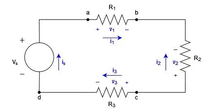
Figure 1
From Figure 1, we are able to quickly identify the unknown variables: vs , is , v1 , i1 , vs , i2 , v3 and i3
To apply Kirchhoff's current law effectively, it is necessary to designate an algebraic sign and charge sign to each current at the node(s) in question, corresponding to a predetermined reference direction. We can assign a positive sign to a charge entering a node and a negative sign indicating the charge exiting the node. The inverse can also be done, by assigning a negative sign to a charge entering a node and a positive sign indicating the charge exiting the node. This needs to be done to accurately describe the circuit and calculate the current flowing around any point in the system.
When utilizing KCL to analyze the circuit depicted in Figure 1 and employing the approach in which currents that exit a node are assigned a positive value, a total of four questions can be derived from the four nodes present in the circuit:
|
Node |
Equation |
|
a |
i1 - is = 0 |
|
b |
-i1 - i2 = 0 |
|
c |
i2 + i3 = 0 |
|
d |
is - i3 = 0 |
Kirchhoff's Current Law in a Series Circuit
A series circuit is identified when a circuit element follows after another, sharing only one terminal connection.
In a series electrical circuit, every component in the circuit experiences an identical amount of current. This can be attributed to the fact that there exists only one path for the current to flow through. Analogous to how water flows through a tube, electrical charge flows through conductors, and the rate of this flow (akin to the speed of the water) must remain consistent at any given point in the circuit, and at any specific point in time.
We will use Figure 2 to evaluate the current and voltage relationship.
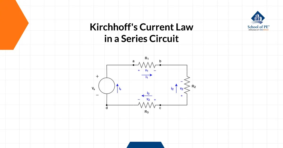
Figure 2
Since the circuit is a closed loop and in series, we have:
is = i1 = i2 = i3 (1)
Ohm's Law (I = V/R) can be applied to find the current.
-Vs + i1R1 + i2R2 + i3R3 = 0 (2)
Substituting Equation 1 into Equation 2, we can express the
-Vs + is ( R1 + R2 + R3 ) (3)
is = Vs ⁄ R1 + R2 + R3 (4)
Kirchhoff's Current Law in a Parallel Circuit
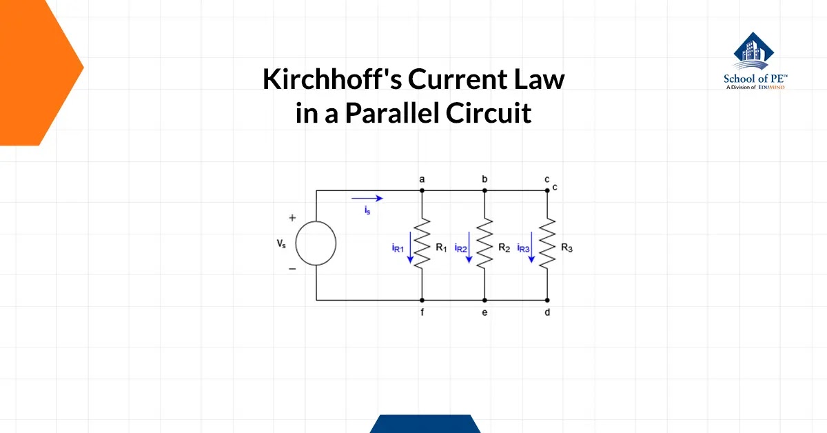
Figure 3
A parallel circuit is categorized when circuit elements share more than one terminal connection.
Just like in a series circuit, Ohm's law follows the same principle, whereby the values assigned to voltage, current, and resistance must be of the same contextual relevance to ensure accurate calculations (CIRCUIT TOPOLOGY AND LAWS - Applied Industrial Electricity, n.d.). Discrepancies in contextual frameworks may lead to erroneous results and unreliable data, underscoring the need to maintain consistency across all parameters.
From Figure 3, we apply Ohm's Law to find the current in each resistor with the given voltage source, vs.
iR1 = vs ⁄ R1 (5)
iR2 = vs ⁄ R2 (6)
iR3 = vs ⁄ R3 (7)
Although the source current for a parallel circuit remains unknown at this stage, with further derivation of the characterization equations, it becomes evident that the total current is equal to the sum of all individual resistor currents or "branches". From the node section, "assign a positive sign to a charge entering a node and a negative sign indicating the charge exiting the node. The inverse can also be done, by assigning a negative sign to a charge entering a node and a positive sign indicating the charge exiting the node", we can derive the final characterization equation.
is = iR1 + iR2 + iR3 (8)
Conclusion
Kirchhoff's Current Law is a fundamental principle in electrical engineering and physics that states that the total current entering a node or junction in a circuit must be equal to the total current leaving that node. This law is based on the law of conservation of charge and is essential for analyzing and understanding electrical circuits. By applying KCL and Ohm's Law, engineers and physicists can calculate the currents and voltages at any point throughout a circuit and verify that they are consistent with the circuit's design specifications.
Interested in becoming an electrical engineer? Register for an FE or PE Electrical exam review course with School of PE today and join our tens of thousands of students who have passed their engineering exams!
No comments :
Post a Comment