


 FE Courses
 PE Courses
 SE Courses
 Continuing Education
 Pmp Courses
 Corportate Training
Table of Contents
1. Introduction
Kirchhoff's laws are basic analytical tools used to obtain solutions for currents and voltages in an electrical circuit. Circuits may be from a direct-current system or from an alternating current system. The following diagram depicts a simple resistive network.

|
| Figure: Simple Resistive Network |
Kirchhoff's laws of circuit analysis are reviewed in our FE Electrical exam review course. Kirchhoff's Current Law (KCL) and Kirchhoff's Voltage Law (KVL) are important for both DC and AC steady states, and they are important to understand for the FE exam.
2. Parts of an Electrical Circuit
(i) Node: In an electrical circuit, a node is the point where two or more components are connected. This point is usually marked with a dark circle or dot when being depicted on diagrams. The circuit in the diagram above includes nodes, which are labeled as "b" and "g." A point, or a node in a circuit, specifies a certain voltage level with respect to a reference point or node.
(ii) Branch: A branch is a traversing path between any two nodes in a circuit that have electrical elements. The above diagram shows that the circuit has seven branches, of which four are resistive branches (a-c, a-b, b-c, and b-g), and the other three branches contain voltage and current sources (a-b, a-g, and c-g).
(iii) Loop: A loop is any closed path in an electrical circuit. A loop in a circuit consists of branches that have a beginning point and an end point for tracing the path of electricity. In the above diagram, loops/closed paths include a-b-g-a and a-c-b-a. Further, it may be noted that the outside closed paths are a-c-g-a and a-b-c-g-a.
(iv) Mesh: A mesh is a special loop that does not include any other loops within it. The above diagram indicates that the three loops (a-b-g-a, b-c-g-b and a-c-b-a) are also considered meshes, while the loops a-c-g-a and a-b-c-g-a are not considered meshes.
3. Kirchhoff's Current Law:
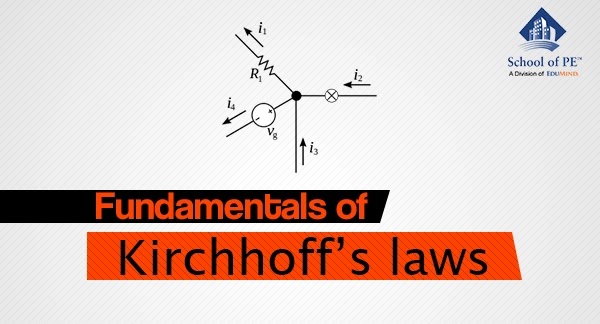
KCL states that at any node in a circuit, the algebraic sum of currents entering and leaving a node at any instant of time must be equal to zero. Currents entering and currents exiting the node must be assigned opposite algebraic signs to assure the resultant equates to zero. Example: In the following figure, I1 - I2 + I3- I4 + I5 - I6 = 0.

|
| Figure: Kirchhoff's Current Law |
4. Kirchhoff's Voltage Law
KVL states that in a closed circuit, the sum of all source voltages must be equal to the sum of all voltage drops. Voltage drops occur when the current flows from the higher potential terminal toward the lower potential terminal. Voltage rise occurs when current flows from a lower potential terminal toward the higher potential terminal or positive terminal of voltage source.
Kirchhoff's Voltage Law from the figure: in clockwise direction starting from the voltage source is: V1 - IR1 - IR2- V2- IR3- IR4 + V3 - IR5 - V4 = 0, V1 - V2 + V3 - V4 = IR1 + IR2 + IR3 + IR4 + IR5

|
| Figure: Kirchhoff's Voltage Law |
Engineers preparing for the Fundamentals of Engineering Electrical and Computer exam should review Kirchhoff's laws prior to the exam in order to be able to estimate currents and voltages in an electrical circuit.
No comments :
Post a Comment