Thursday, 10 August 2017

Basic Types of Residential Drainage Systems

Drainage is the method of removing surface or sub-surface water from a given area. Drainage systems include all of the piping within a private or public property that conveys sewage, rainwater, and other liquid waste to a point of disposal. The main objective of a drainage system is to collect and remove waste matter systematically to maintain healthy conditions in a building. Drainage systems are designed to dispose of wastewater as quickly as possible and should prevent gases from sewers and septic tanks from entering residential areas.
Basic Types of Residential Drainage Systems


1. Residential Drainage Systems

Residential drainage systems remove excess water from residential areas. This system helps whisk water away from walkways, driveways, and roofs to avoid flooding. Residential drainage systems are very important as they prevent rotting, mold, mildew, and structural damage in buildings from a buildup of water. Our SE exam review courses discuss the requirements and recommendations for residential structures regarding drainage systems.

The types of residential drainage systems are:

  1. Surface
  2. Subsurface
  3. Slope
  4. Downspout/gutters

2. Surface Drainage Systems

Surface drainage systems contain shallow ditches dug in a parallel pattern, which act as canals for run-off water. Theses ditches lead the water into the main drain to avoid water pooling and flooding.

3. Subsurface Drainage Systems

A subsurface drainage system is also known as a French drain. Subsurface drains are placed beneath the top layer of soil to remove excess water at the root level. Subsurface drains require the digging of deep ditches and the installation of underground pipes. A large collector drain is installed to collect water from the pipes.

4. Slope Drainage Systems

Slope drains allow water to flow downward from a structure with the aid of pipes moving down a slope. A pipe is installed and anchored into a small incline, which causes water to flow through the pipe and away from the structure. 

5. Downspout and Gutter systems

Downspouts collect water from gutters and divert it to the ground. A downspout is typically connected to a gutter system on a building and carries water away from the roof down to the ground. Downspouts empty out the water on a slope so that the water does not pool at the base of the downspout. 

Combined drainage systems use a single drain to convey both water from sanitary usage and rainwater from roofs and other surfaces to a shared sewer. This system is economical to install. Separate drainage systems use separate foul water drains that lead to a sanitary sewer. The rainwater from roofs and other surfaces is conveyed in a separate surface water drain into a surface water sewer. This system is relatively expensive to install. Our SE exam review courses thoroughly review the building and design codes to follow proper drainage system installations.

Thursday, 29 June 2017

Applications of Spread Footing and Soil Pressure Distribution


1. Introduction

The size and weight of a building as well as the nature of the soil structure it is built on play a critical role in foundation design. Soil pressure distribution must be addressed to ensure a sound structure. Spread footing is a crucial structural component that provides strength for a building's foundation.

2. Definition of footings

Footing is a structural element that transfers a building's weight to the soil using columns, walls, and lateral loads from earth-retaining structures. Our PE Civil exam review course discusses footings and their physical characteristics for engineers preparing for the PE Civil exam.

Applications of Spread Footing and Soil Pressure Distribution

3. Importance of Spread Footings

  1. A spread footing foundation has a wider bottom portion compared to a load-bearing foundation; the wider bottom "spreads" the weight of the structure over a larger area for greater stability. 
  2. While traditional spot footings only have a single point of contact with the foundation, spread footings extend support continuously across the entire building layout. 
  3. Spread footings are used to support a foundation or set of piers below a building. 
  4. To add additional support, spread footings are constructed with concrete and reinforced with steel. Since spread footing transfers the weight of the building over a large area, spread footings have little risk of failure compared to spot footers. 
  5. Spread footing extends the life of a building by minimizing structural damage. Footings must be designed to carry the column loads and transmit them to the soil safely. 
  6. Spread footings may be circular, square, or rectangular. 
  7. Spread footings are common in residential construction.

4. Mode of Distribution of Soil Pressure in a Spread Footing

Column loads act at the center of the footing, creating a uniform surface for the soil underneath the footing area. The distribution of pressure depends on the composition of the soil and on the degree of flexibility of the footing. 

5. Types of Spread Footings:

(i) Isolated Footing
When columns are spaced far apart, isolated footings are used to support single columns. 

(ii) Combined Footing
When two columns are close to each other and their individual footings overlap, a combined footing is required. A combined footing supports two columns so that the load is evenly distributed. A combined footing may be rectangular or trapezoidal.

(iii) Strap Footing (Cantilever)
In strap footing, two isolated footings are connected with a structural strap (rigid beam) or lever. 

(iv) Mat Foundation (Raft)
A mat foundation is a large slab that supports several columns and walls under the entire structure. If several columns overlap each other, then a single footing for all columns is provided. This type of footing is known as mat footing. Mat foundations are used to reduce the differential settlements on non-homogeneous soils. 

Applications Of Spread Footing

Wednesday, 21 June 2017

Basic Principles and Classifications of Pile Foundations


1. Introduction

Shallow and deep foundations signify the relative depth of the soil on which buildings are founded. When the depth of a foundation is less than the width of the footing and is less than ten feet deep, it is a shallow foundation. Shallow foundations are used when surface soils are strong enough to support the imposed loads. If the depth of a foundation is more than the width of the building foundation, it is a deep foundation. Deep foundations are often used to transfer building loads deeper into the ground. 

Basic Principles and Classifications of Pile Foundations

2. Conditions where deep foundations are used

  • Soil near the surface that has relatively weak bearing capacities (700 pounds per square foot or less)
  • Soils near the surface that contain expansive clays (shrink/swell soils) 
  • Surface soils that are vulnerable to being removed by erosion or scour

3. Classification of deep foundations 

Deep foundations are classified into three categories:

  • Pile foundations
  • Well foundations
  • Caisson foundations

Types of foundations and basic mechanisms involved in the classification of deep foundations are reviewed in our FE Civil exam review course for those preparing to become an engineer in training.

4. Pile foundations

A pile foundation is defined as a series of columns constructed or inserted into the ground to transmit loads to a lower level of subsoil. A pile is a long cylinder made up of a strong material, such as concrete. Piles are pushed into the ground to act as a steady support for structures built on top of them. Piles transfer the loads from structures to hard strata, rocks, or soil with high bearing capacity. The piles support the structure by remaining solidly placed in the soil. As pile foundations are set in the soil, they are more tolerant to erosion and scour.

5. Installation of pile foundations 

Piles are first cast at ground level and then hammered or driven into the ground using a pile driver. A pile driver is a machine that holds the pile vertical and hammers it into the ground. Blows are repeated by lifting a heavy weight and dropping it on top of the pile. Piles should be hammered into the ground until the refusal point is reached, which is the point where a pile cannot be driven into the soil any farther. The method of installing a pile is a major consideration in the structural integrity of pile foundations. The driven-pile method is an ideal option because it least disturbs the supporting soil around the pile and results in the highest bearing capacity for each pile. Since every pile has a zone of influence on the soil around it, piles must be spaced far enough apart from each other so that the loads are distributed evenly.

6. Categories of piles

Depending on their function, piles are classified as bearing piles, friction piles, friction-cum-bearing piles, batter piles, guide piles, and sheet piles.

Based on the composition of materials, piles are classified as timber piles, concrete piles, sand piles, or steel piles. 

1)Bearing piles are driven into the ground until a hard stratum is reached. Bearing piles rest on hard strata and act as pillars to support the structure. Bearing piles allow vertical loads and transfer the building load to the hard stratum underneath. 

2)Friction piles are used when the soil is soft and there are no hard strata available. These piles are long, and the surfaces are roughened to increase surface area and increase frictional resistance. They bear on frictional resistance between their outer surface and the soil in contact. Friction piles do not rest on hard strata. 

3)Batter piles are driven inclined to resist inclined loads.

4)Guide piles are used in the formation of cofferdams to provide stable foundations for under-water construction.

Basic principles of pile foundations and their classifications are recommended topics to review prior to taking the FE Civil exam. 

7. Types of piles based on shape and composition

Types of piles based on shape and composition

Wednesday, 14 June 2017

The Conduction Process and its Importance in Mechanical Engineering Applications


1. Introduction

Regions with greater molecular kinetic energy pass their thermal energy into regions with less molecular energy through direct molecular collisions. This process is known as conduction. In metals, a significant portion of the transported thermal energy is carried by conduction-band electrons.

2. Definition of Conduction

Conduction is the transfer of thermal energy that does not have any flow of material medium and is the main process by which thermal energy is transferred from one solid to another. Our PE Mechanical course reviews the physical properties of heat.

The Conduction Process and its Importance in Mechanical Engineering Applications

3. Importance of Heat Transfer Conduction

Sticking a metal pole into a fire is an example of heat transfer conduction. Particles at the heated end vibrate vigorously. They collide with the neighboring particles and transfer their energy. Eventually, the particles at the cooler end are set into vigorous vibration, which causes the entire metal pole to become hot.

4. Types of conduction

There are two types of conduction:
1)Molecular vibration
2)Free electron diffusion

(i) Molecular Vibration

When heat is supplied to one end of an object, the molecules at that end start to vibrate vigorously. During this process, they bump into their neighboring molecules, which transfers some energy. The receiving neighbor molecule gains energy and starts to vibrate more vigorously. The cycle continues.

(ii) Free Electron Diffusion

This form of conduction takes place only in metals because only metals have free electrons. Electrons are freed from a molecule when heat is applied, which forces the electrons to travel toward the colder end of the metal. At the colder end, the electrons collide into many molecules, and therefore, pass energy to the molecules at the other side.

5. Conduction in Metals

In solids, thermal energy is transferred through the vibration and collision of particles. However, in metals, due to the presence of free electrons, thermal energy is spread through electron diffusion. Electrons gain kinetic energy and move rapidly and collide with the atoms in the cooler parts of the metal to pass on their energy.

The process of conduction in metals is important for engineers to understand when preparing to pass the PE Mechanical exam.

6. Fourier's Law of Heat Conduction

The law of heat conduction, or Fourier's law, states that the time rate of the heat transfer through the material is proportional to the negative gradient in the temperature and to the area.

Q = -kA(dT/dx)
'Q' - heat flow rate by conduction (W)

'k' - thermal conductivity of body material (W m-1 K-1)

'A'- cross-sectional area normal to direction of heat flow (m2) and 'dT/dx' is the temperature gradient (k-m-1)

The negative sign in Fourier's equation indicates that the heat flow is in the direction of negative gradient temperature, which makes the heat flow positive

The thermal conductivity "k" refers to the transport properties 

Thermal conductivity "k" provides indication of the rate at which heat energy is transferred through the medium by the conduction process 

7. Applications of Conduction Phenomena in Engineering

  1. Mechanical Engineering Equipment
  2. Home Appliances
  3. Boilers

Wednesday, 7 June 2017

Types and Sources of Air Pollution

Air pollution is defined as the presence of any particle or gas found in the air that is not part of the original composition. Air pollution is a change in the physical, chemical, and biological characteristics of the air surrounding us. The substances that cause air pollution are called air pollutants, and they may be in the form of a gas, liquid, or solid.

Types and Sources of Air Pollution

Air pollutants are transboundary in nature as they travel and affect areas far away from their point of origin. Air pollution causes adverse effects on humans and other living organisms. Our PE Environmental exam review course thoroughly reviews the types and sources of air pollution for those preparing for the PE Environmental exam.

Air Quality Index

Air quality index (AQI) indicates whether pollutant levels in the air may cause health concerns. AQI ranges from 0 to 500, with a higher number meaning a lower air quality.

The table below provides the AQI limits for human health.


Air Quality Index
Air Quality
Air Quality Index Range
Good
0-50
Moderate
51-100
Unhealthy for sensitive groups
101-150
Unhealthy
151-200
Very unhealthy - ALERT
201-500

The air quality index table is a useful reference for environmental engineers preparing to take the PE exam.

Types of Air Pollutants

Air pollutants may be natural, such as wildfires, or may be synthetic (manmade). Air pollutants are classified as primary pollutants and secondary pollutants. 

(i) Primary air pollutants are emitted directly into the atmosphere by the original source
(ii) Secondary air pollutants are formed because of reactions between primary pollutants and other elements in the atmosphere, such as the ozone.

The common air pollutants are discussed below:

  1. Carbon Monoxide - Carbon monoxide is a colorless, odorless gas. Carbon monoxide can be present in car exhaust and smoke. Carbon monoxide deprives humans of their oxygen supply, which causes headaches, fatigue, impaired vision, and even death.
  2. Sulfur Dioxide - Sulfur dioxide is produced when coal and fuel oils are burned and is also present in power plant exhaust. Exposure to sulfur dioxide narrows the airways in the respiratory system, which causes wheezing and shortness of breath. 
  3. Nitrogen Dioxide - Nitrogen dioxide is both a primary and secondary air pollutant. Nitrogen dioxide is created when nitrogen reacts with oxygen in the atmosphere. Nitrogen dioxide can cause respiratory infections and other respiratory problems.
  4. Particulate Matter - Particulate matter contains particles of different sizes that are released into the atmosphere from various sources, including fossil fuels, dust, smoke, and fog. Particulate matter can accumulate in the respiratory system, which can aggravate the heart and lungs and increase the risk of respiratory infections.
  5. Ground-Level Ozone - Ground-level ozone is formed from automobile, power, and chemical plant exhausts. Ground-level ozone irritates the respiratory system and causes asthma by reducing lung function.
  6. Smog - Smog is the combination of gases with water vapor and dust and forms when heat and sunlight react with gases, which is known as photochemical smog. 

Tuesday, 30 May 2017

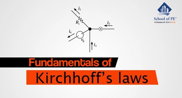
FUNDAMENTALS OF KIRCHHOFF'S LAWS FOR ELECTRICAL ENGINEERS


1. Introduction

Kirchhoff's laws are basic analytical tools used to obtain solutions for currents and voltages in an electrical circuit. Circuits may be from a direct-current system or from an alternating current system. The following diagram depicts a simple resistive network.
Simple Resistive Network
Figure: Simple Resistive Network

Kirchhoff's laws of circuit analysis are reviewed in our FE Electrical exam review course. Kirchhoff's Current Law (KCL) and Kirchhoff's Voltage Law (KVL) are important for both DC and AC steady states, and they are important to understand for the FE exam.

FUNDAMENTALS OF KIRCHHOFF'S LAWS FOR ELECTRICAL ENGINEERS

2. Parts of an Electrical Circuit

(i) Node: In an electrical circuit, a node is the point where two or more components are connected. This point is usually marked with a dark circle or dot when being depicted on diagrams. The circuit in the diagram above includes nodes, which are labeled as "b" and "g." A point, or a node in a circuit, specifies a certain voltage level with respect to a reference point or node.

(ii) Branch: A branch is a traversing path between any two nodes in a circuit that have electrical elements. The above diagram shows that the circuit has seven branches, of which four are resistive branches (a-c, a-b, b-c, and b-g), and the other three branches contain voltage and current sources (a-b, a-g, and c-g).

(iii) Loop: A loop is any closed path in an electrical circuit. A loop in a circuit consists of branches that have a beginning point and an end point for tracing the path of electricity. In the above diagram, loops/closed paths include a-b-g-a and a-c-b-a. Further, it may be noted that the outside closed paths are a-c-g-a and a-b-c-g-a.

(iv) Mesh: A mesh is a special loop that does not include any other loops within it. The above diagram indicates that the three loops (a-b-g-a, b-c-g-b and a-c-b-a) are also considered meshes, while the loops a-c-g-a and a-b-c-g-a are not considered meshes.

3. Kirchhoff's Current Law:

KCL states that at any node in a circuit, the algebraic sum of currents entering and leaving a node at any instant of time must be equal to zero. Currents entering and currents exiting the node must be assigned opposite algebraic signs to assure the resultant equates to zero. Example: In the following figure, I1 - I2 + I3- I4 + I5 - I6 = 0. 
Kirchhoff's Current Law
Figure: Kirchhoff's Current Law

4. Kirchhoff's Voltage Law

KVL states that in a closed circuit, the sum of all source voltages must be equal to the sum of all voltage drops. Voltage drops occur when the current flows from the higher potential terminal toward the lower potential terminal. Voltage rise occurs when current flows from a lower potential terminal toward the higher potential terminal or positive terminal of voltage source. 

Kirchhoff's Voltage Law from the figure: in clockwise direction starting from the voltage source is: V1 - IR1 - IR2- V2- IR3- IR4 + V3 - IR5 - V4 = 0, V1 - V2 + V3 - V4 = IR1 + IR2 + IR3 + IR4 + IR5
Kirchhoff's Voltage Law
Figure: Kirchhoff's Voltage Law

Engineers preparing for the Fundamentals of Engineering Electrical and Computer exam should review Kirchhoff's laws prior to the exam in order to be able to estimate currents and voltages in an electrical circuit.

Monday, 22 May 2017

The Importance of Geology in Structural Engineering


1. Introduction

Geology is the study of the earth, its origin, structure, composition, and history. There are many forms of geology, including economic geology, planetary geology, and engineering geology. Engineering geology is a very important topic for structural engineers to understand as it helps them properly plan a project when considering the design, location, and other important geological factors.

The Importance of Geology in Structural Engineering

2. Importance of Engineering Geology

Engineering geology helps ensure a safe and cost-effective design for construction projects. Gathering geological information for a project site is important in the planning, design, and construction phase of an engineering project. Conducting a detailed geological survey of an area before commencing a project will reduce the overall cost of the project. Common foundational problems in dams, bridges, and other buildings are typically directly related to the geology of the area where they were constructed. Our SE exam review course provides adequate geological information for engineers preparing for the SE exam.

3. The Need for an Understanding of Geology 

For quality control of construction materials, such as sand, gravel, or crushed rocks, an engineer with a geological background is needed. The knowledge of the nature of the rocks in a specific area is necessary for tunneling and determining the stability of cuts and slopes. Geological maps also help in planning projects. If geological features, such as faults, joints, beds, folds, or channels are encountered, suitable remedies should be incorporated. Geological maps provide information regarding the structural disposition of rock types in a proposed area. Topographical maps are essential for understanding the advantages and disadvantages of all possible sites. 

Hydrological maps provide information regarding the distribution of surface water channels and the occurrence and depth contour of ground water. Knowledge of ground water is necessary for excavation works. Understanding soil erosion transportation and deposition by surface water helps in soil conservation, river control, and coastal works. In geologically-sensitive areas, such as coastal belts and seismic zones, knowledge of the geological history of the area is very important. It is recommended that those preparing for one of the SE exams have a thorough understanding of geology and how to evaluate a site before a construction project.

Wednesday, 17 May 2017

Soil Erosion: Its Causes and Effects


1. Introduction

Soil is considered to be one of the most valuable natural resources. Soil is a combination of weathered rock, decayed organic matter, mineral fragments, water, and air. As degraded soil becomes loose and weak, it loses the ability to absorb and retain water, which leads to soil erosion. Ellison (1944) defines soil erosion as the process of detachment and transport of soil particles by erosive agents. 

Soil Erosion: Its Causes and Effects

2. Soil Erosion Factors

Factors that contribute to erosion include climate, topography, soil characteristics, vegetation, velocity of winds, rainfall intensity, and duration. Knowing the factors that cause erosion assists in identifying the source of erosion and developing a plan to control it. 

Erosion is classified into two major categories: geological erosion and man-made erosion. Geological erosion occurs naturally, while man-made erosion arises when humans alter the land. Soil classification and soil erosion factors are discussed in our FE Environmental exam review course to recap the fundamentals and factors of soil erosion.

3. Agents of Soil Erosion

Agents of Soil Erosion

4. Soil Erosion by Water

When a raindrop hits the soil, it destroys the granulation of soil (compaction) and causes a disruption of the soil surface (detachment). The exposed soil particles are dislodged, splashed into the air, and suspended in the rainwater. The rainwater that runs from a slope during heavy rains is referred to as a runoff. This runoff carries away soil particles and nutrient elements along with it.

There are three main types of erosion that occur due to water:

i) Sheet erosion is the uniform movement of a thin layer of soil from unprotected land.

ii) Rill erosion forms when the rainfall is heavy and runoff volume increases. Runoff rain water creates many small, deep channels called rills.

iii) Gully erosion evolves from rill erosion over time. When runoff is in a single wide and deep channel, it is known as gully erosion. A gully is defined as a scoured-out area that is not crossable with tillage and grading equipment.

Soil erosion by water is thoroughly discussed in our FE Environmental exam refresher course.

5. Wind Erosion

Wind erosion occurs when land that is bare of vegetation is exposed to high-velocity winds. Soil movement is initiated when the forces of wind are exerted against the surface of the ground. 

For each soil type and surface condition, there is a minimum velocity required to move soil particles; this concept is known as threshold velocity. When wind threshold velocity overcomes the cohesive and gravitational forces of the soil particles, wind can move soil and carry it away in suspension.

6. Other Forms of Soil Erosion

Gravity erosion is the transfer of rock and soil down a slope due to the direct action of gravity; gravity erosion can cause a mass movement of soil, ice, and rock, which leads to landslides, avalanches, and rock fall. 

Glacier erosion occurs when a huge mass of ice slowly moves over the land. Glaciers erode the earth's surface and wear down, pick up, and carry sediments that vary in size. 

Sedimentation control methods and the effects of soil erosion are important concepts to understand for the FE Environmental exam.

Wastewater Treatment Methods


1. Introduction

Water is an ideal solvent with a neutral pH value and is colorless, odorless, and tasteless in its purest form. Any physical or chemical change in water that affects the health of a living organism is known as water pollution. Water can become contaminated due to domestic, industrial, physical, chemical, and biological pollutants. 

Water pollution is a global problem affecting millions of lives.

  1. 1.8 billion people do not have access to clean water
  2. 70% of all industrial waste is dumped into bodies of water
  3. 2 million tons of sewage is disposed of into bodies of water each day throughout the world 
  4. 840,000 people die each year from water-related diseases

Wastewater Treatment Methods

2. Sources of Water Pollution

Water pollution comes in different forms and from different sources. 

  1. Point-source pollution: pollutants derived from a single-known source (pipe or sewer line)
  2. Nonpoint-source pollution: pollutants that come from many unknown sources (agricultural run-off)
  3. Trans-boundary pollution: pollutants that affect the environment hundreds of miles away from the source (nuclear incident)

Water pollution and the causes of water pollution are thoroughly reviewed in our PE Environmental exam review courses.

3. Wastewater Treatment 

The water used for industrial and domestic purposes is degraded with pollutants, and such water must be treated to remove pollutants before being released into bodies of water. The aim of wastewater treatment is to remove suspended solids, salts, nutrients, bacteria, and oxygen-demanding material. Wastewater treatment is a large industry that is worth $20 billion a year. Therefore, it is important to study wastewater treatment methods prior to taking the PE exam. 

4. Methods of Wastewater Treatment

Wastewater is treated by using different methods to remove pollutants before returning the water to the drinking supply.

Two methods of water treatment are employed based on the need: 

  1. Conventional method using sewage tanks
  2. Centralized wastewater treatment plants

Wastewater treatment involves three stages: 

  • Primary stage
  • Secondary stage 
  • Tertiary stage 

The three stages involved in wastewater treatment are explained in the following flow charts:

Raw Sewage

Wastewater Treatment

(i) Primary Treatment

Screening stage: Incoming raw sewage enters the treatment plant and passes through a series of screens to remove large, floating organic material.

Sedimentation stage: In the second stage, water enters the sedimentation tanks to remove sand, small stones, and grit. The particulate matter settles out to form a mud called sludge. In the next step, sludge is removed and transported to a digester. Primary treatment removes about 35% of biochemical oxygen demand (BOD) from the polluted water. 

(ii) Secondary Treatment

Secondary treatment is a biological process involving microorganisms. The wastewater is pumped into oxidation ponds where the microorganisms oxidize its organic matter, and then it is transferred from the primary sedimentation tank to the stabilization tank. The partly-treated water then enters the final sedimentation tank where the sludge settles. After the sludge is settled, it is transported to the digester.

(iii) Chlorination Stage

At this stage, the pH value of the water is near neutral. The BOD value of water is assessed, and the chlorination process is activated to kill harmful pathogens. After chlorination, water that is safe to use can be discharged. Secondary treatment removes about 90% of BOD. Secondary treatment does not remove all nutrients, heavy metals, solvents and pesticides. To be cautionary in regards to safety, water should be treated in an advanced stage that involves sophisticated methods and technology.

(iv) Tertiary Treatment

Tertiary treatment is a physicochemical process aimed to remove the turbidity of wastewater caused by nitrogen, phosphorus, dissolved organic matter, heavy metals, and pathogens. Tertiary treatment involves a chemical oxidation of wastewater using strong oxidizing agents, such as chlorine gas, perchlorate salts, ozone gas, and UV radiation. Tertiary treatment renders the water safe to be discharged back into the environment. 

Wastewater treatment topics are extensively discussed and emphasized in our PE exam review courses for both environmental engineers and water resources engineers.

Thursday, 27 April 2017

The Importance of Soil Erosion Control Measures

Soil erosion control is the process of minimizing the potential for soil erosion. Erosion control measures have proven to reduce erosion potential by stabilizing exposed soil and reducing surface runoff flow velocity. 

Erosion and sediment control measures are classified into two categories:
1. Temporary control measures
2. Permanent control measures

Temporary soil erosion control measures are created to control soil erosion during the construction phase. Once the project has been completed and permanent measures have been installed, the temporary measures are completely removed.

Permanent soil erosion control measures are incorporated into the overall design to address long-term post-construction erosion and sediment control. Soil erosion control measures and stormwater management practices are thoroughly reviewed in our PE Civil exam review courses

The Importance of Soil Erosion Control Measures

Erosion Control Methods:

Source control of runoff flow

The primary goal of source control is to protect exposed earth surfaces from the erosive energy of rain splash and surface runoff flow. Cover is the most effective erosion control method for preventing soil erosion. Cover includes top soiling in conjunction with one or more of the following methods: seeding, mulching, hydroseeding, sodding, erosion control blankets, turf reinforcement matting (TRM), riprap, gabion mat, aggregate cover, and paving.

Runoff control during project work

During the construction of a project, it is not possible to provide surface cover for all disturbed areas. Runoff control methods, such as slope surface modification and slope gradient reduction, are employed to prevent soil erosion. 

Bio-engineering methods

Revegetation of exposed soil with grass and plant growth on topsoil is the main bio-engineering soil erosion control method. This method is a permanent soil erosion control measure that uses the roots, stems, and leaves of vegetation to reduce the potential for soil erosion. 

Bio-engineering involves the introduction of foliage that decreases the impact of rain, leading to infiltration of rainwater into the soil and resulting in anchoring the soil with root systems. As the plants grow, the bio-engineered erosion control system continues to strengthen. Bio-engineering methods provide a simple and cost-effective measure for controlling long-term erosion problems.

Terracing

Terracing prevents and reduces erosion caused by surface runoff by decreasing the incline and length of hillside slopes. Terracing is a land shaping method in which earth embankments and ridges are redesigned for the interception of runoff water, which in turn channels it into a specific direction and outlet. Terraces can be classified by two types: bench and broad base terraces. The bench terrace is the oldest form of terrace and is used to reduce land slope; broad base terraces are used to control and retain surface water on sloping land. 

Vegetated waterways 

Vegetated waterways protect soil against the erosive forces of runoff from sloping lands. These waterways absorb the destructive energy, which causes channel erosion and gully formation. Depending on the climate and functional requirements, waterways can have cross sections in parabolic, trapezoidal, and triangular forms.

Contouring

Contouring involves the tillage and planting of crops on the same elevation or "contour." Water is restrained between the contours, which moderates water erosion and increases soil moisture. With stable soils, contouring leads to reduced soil loss. 

Soil erosion is an important topic to understand for the PE Civil exam. Our PE Civil review courses thoroughly discuss soil erosion and the methods used to prevent it.

Monday, 24 April 2017

Effects of Air Pollution on the Environment

Air pollution occurs when harmful gases, dust, or smoke enters the atmosphere and has a negative impact on plants, animals, and/or humans. Air pollution is the deadliest form of pollution, killing millions of people each year. The World Health Organization reports that more than 92% of the world's population lives where air pollution exceeds safe limits. Among all other pollutants, air pollution has proven to be a major concern throughout the world. Air pollution and its impact on the environment creates an increasing demand for environmental engineers with their PE license. 

Effects of Air Pollution on the Environment

Air Pollution Hazards

Air pollution hazards are thoroughly discussed in our PE Environmental review courses


Acid Rain

Acid rain is formed when sulfur dioxide and nitrogen oxide in the atmosphere is mixed with rainwater as a weak sulfuric and nitric acid. Acid rain can damage crops, plants, and aquatic life and is even capable of damaging structures. 

Eutrophication

Eutrophication is a condition created by using excessive fertilizers and pesticides that drain into bodies of water. Nutrients, such as nitrogen, stimulate blooms of algae, which in turn endangers aquatic life.

Haze

Haze is formed when sunlight encounters suspended pollutant particles in the air. Haze obstructs our vision, clarity, color, texture, and form of what we visualize in the real world. 

Negative Effects on Wildlife

Like humans, wild animals are also developing health problems as they are exposed to toxic air. Air toxins contribute to birth defects, reproductive failure, and disease in wild animals and aquatic ecosystems.

Ozone Depletion

Ozone is a gas that is present in the earth's upper atmosphere, the stratosphere. Ozone forms a layer that protects life on Earth from the sun's harmful ultraviolet (UV) rays. Ozone is gradually being destroyed due to ozone-depleting substances being released into the atmosphere. The thinning of the protective ozone layer is causing higher amounts of UV radiation to reach the earth, leading to more cases of skin cancer, cataracts, and impaired immune systems. UV rays also damage crops and lead to reduced yields. 

Crop and Forest Damage

Air pollution damages crops and trees in many ways. Air pollution reduces growth and the survivability of plant seedlings and increases plant susceptibility to disease, pests, and other environmental stresses, such as harsh weather. 

Global Climate Change

The earth's atmosphere is a delicate balance of naturally occurring gases that trap excessive heat from the sun. This greenhouse effect protects and maintains a stable temperature on the planet. Throughout time, humans have disturbed this natural balance by producing greenhouse gases, including carbon dioxide and methane. Thus, the earth's atmosphere is trapping more of the sun's heat, leading to the average temperature to rise. This phenomenon is known as "global warming." Global warming has significant impacts on human health, agriculture, water resources, forests, wildlife, and coastal areas. 

Air pollution and its potential impacts on the environment are fully reviewed in our PE Environmental refresher course.

Sunday, 16 April 2017

Introduction to Basics of Boiler Components for Mechanical Engineers

The most important components of boilers include fuel oil systems, super heaters, and ash removal systems. As a mechanical engineer, it is extremely critical to understand the various components of boilers. Heat transfer is an important topic for undergraduate mechanical engineers preparing to take the FE Mechanical exam to understand. Heat transfer is thoroughly reviewed in our FE Mechanical exam review course. 

Introduction to Basics of Boiler Components for Mechanical Engineers


1. Fuel Oil System

Oil-fired boilers may use a light grade oil, typically diesel, or a heavier grade residual oil that is often referred to as "Bunker Fuel." Light oils have a low viscosity and do not require pre-heating. They are pumped from the storage tank to the burner, which is equipped with an atomizing tip that sprays the oil into the furnace in the form of a fine mist. The mist mixes very rapidly with the combustion air, ensuring efficient and clean furnace operation. Heavy residual fuel oils are viscous and require pre-heating for proper atomization. The most commonly used residual fuels are typically more viscous. The temperature required to achieve optimal atomization may differ between fuels.

2. Super Heaters

Steam leaving the boiler is routed through the super heater element, which is located in a high-temperature zone of the furnace. The moisture quickly evaporates because the steam is no longer in contact with the water in the drum. The actual difference between the saturation temperature and the actual steam temperature is called the degree of superheat. Although superheating does add additional energy to the steam, the primary objective is to provide a margin of safety by ensuring that the steam does not immediately begin to condense prior to giving up its superheat energy component. Super heaters are commonly used in water tube boilers. The nature of the process determines whether a super heater is required; a super heater is not generally used unless there is a specific need.

3. Ash Removal 

Environmental legislation in most jurisdictions imposes strict constraints on particulate emissions. Therefore, removing entrained fly ash is usually a mandatory requirement on solid-fuel boilers. For large boilers, electrostatic precipitators, bag houses, and scrubbers are widely used. One of the most common methods employed on small to medium sized boilers is the multi-cyclone grit arrester; it has low capital costs and a degree of efficiency that will satisfy all but the most stringent requirements. Understanding boiler components and heat transfer mechanisms is critical for the FE Mechanical exam. Our FE Mechanical exam review course thoroughly covers the topics of heat exchangers, boiling, and condensation. 

4. Common Types of Boilers for Engineering Applications 

(i) Fire tube boilers: 

Fire tube boilers have the advantage of relatively low capital and operating costs. These types of boilers are predominantly used in industries and processes that have modest steam demands at low to medium pressure. Physical size constraints impose limits on operating pressure and because of their large mass, fire tube boilers are not well suited to large, rapid changes in steam loads. 

(ii) Water Tube Boilers 

The water circulation through the tubes of a water tube boiler follows a defined path. This process ensures that a relatively small quantity of water will be rapidly distributed by heat, which results in an efficient operation. Water tube boilers can be brought up to working pressure much more quickly than fire tube equivalents.

Monday, 10 April 2017

Measuring Instruments and Their Performance Characteristics


1. Introduction

Measuring instruments are used to measure a quantity. When choosing an instrument, the static calibration and static performance of an instrument must be considered. Our PE Electrical exam review course thoroughly covers what to consider when selecting instruments for a given job.

The characteristics of measuring instruments can be classified into the following categories:

1)Static performance characteristics
2)Dynamic performance characteristics

Measuring Instruments and Their Performance Characteristics

2. Static Calibration

Static calibration refers to the procedure where an input is constant or a variable is applied to an instrument. Instruments are manufactured based on the property of irreversibility or directionality. This implies that change in an input quantity will cause a corresponding change in the output. A calibration standard must be at least ten times more accurate than the instrument to be calibrated.

Static performance characteristics include the linearity performance of the instrument, static sensitivity of the instrument, repeatability of the same results, hysteresis resolution, and the readability of the results. 

Static performance characteristics influence data acquisition if the instruments are not properly calibrated prior to the measurement. Understanding quality control and quality assurance procedures for handling equipment is essential for the PE exam.

3. Linearity

If the relationship between the output and input can be expressed by the equation Q0= P + RQ1, where P and R are constants, then the instrument is considered linear. Linearity is never fully achieved in real-world situations, and the deviations from the ideal are referred to as linearity tolerances. For example, 3% independent linearity means that the output will remain within the values set by two parallel lines spaced ± 3% of the full-scale output from the idealized line. If the input-output relationship is not linear for an instrument, it may still be approximated to a linear form when it is used over a very restrictive range. 

4. Static Sensitivity

Static sensitivity can be defined as the slope of a calibration curve. 

Sensitivity = Q0/Q1

Sensitivity influences the input parameters of an instrument. The sensitivity factor can also be referred to as sensitivity drift or scale factor drift. 

5. Repeatability Error 

When an instrument is used to measure the same or an identical input many times and at different time intervals, the output is never the same; it deviates from the recorded values. This deviation from the ideal value is referred to as repeatability error.

6. Hysteresis-Threshold Resolution

When testing an instrument for repeatability, it is often noted that the input-out value does not coincide with the inputs, which are continuously ascending and descending values. This occurs because of hysteresis, which is caused by internal friction, sliding, external friction, and free play mechanisms. Hysteresis can be eliminated by taking readings corresponding to the ascending and descending values of the input and calculating their arithmetic mean.

Professional engineers who work with measurements and instrumentation should understand calibration procedures of various instruments for proper data acquisition.